background image

1 8

3062087_0207

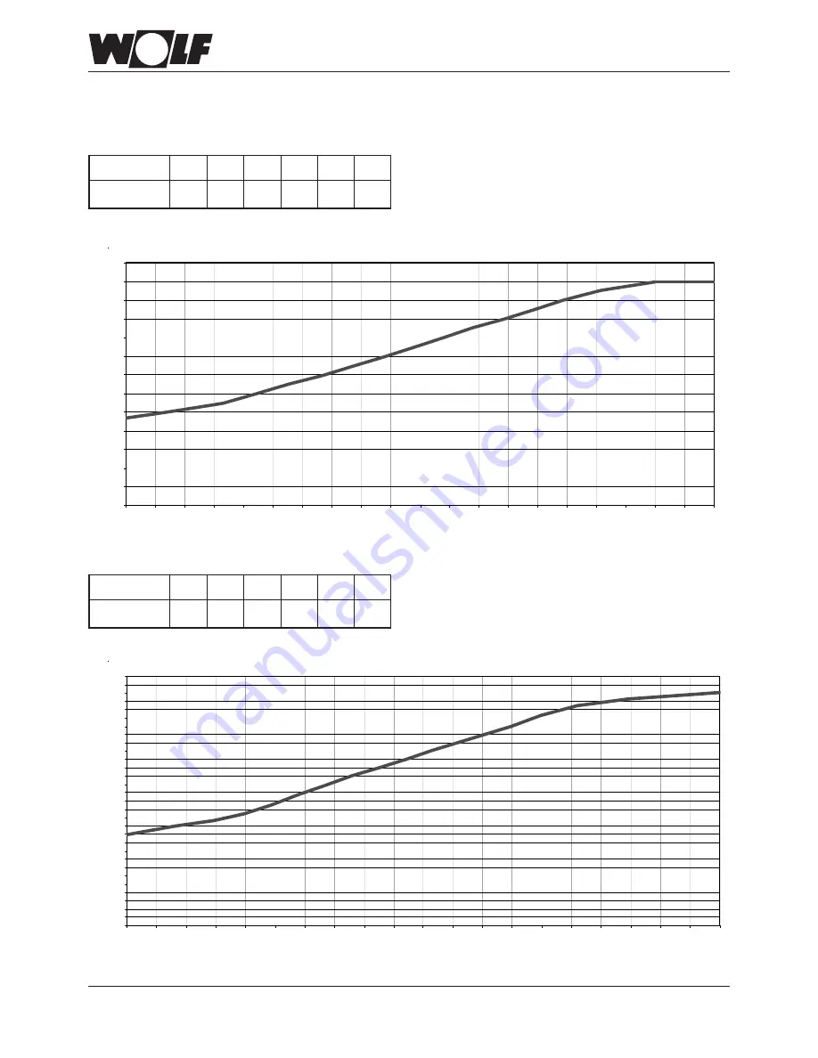
Limiting the maximum output

The output setting can be modified with Wolf control accessories with eBUS capability via parameter HG 04.
The heating output will be determined by the modulation current of the the gas valve. By reducing the modulation current in accordance
with the table, the maximum output will be matched at 80/60 °C to natural gas H and LPG.

0

2

4

6

8

10

12

14

16

18

20

22

24

26

0

5

10

15

20

25

30

35

40

45

50

55

60

65

70

75

80

85

90

95

100

Output [kW]

Modulation current [%]

Output change CGG-1K-24   G31 / G30 / G20

Output [kW]

Modulation current [%]

Output change CGG-1K-28   G31 / G30 / G20

0

1

2

3

4

5

6

7

8

9

10

11

12

13

14

15

16

17

18

19

20

21

22

23

24

25

26

27

28

29

30

0

5

10

15

20

25

30

35

40

45

50

55

60

65

70

75

80

85

90

95

100

Output [kW]

10.9

14

18

22

26

28

Mod

 [%]

1

22

38

56

73

100

Output [kW]

9.4

12

15

18

21

24

Mod

 [%]

1

22

39

54

69

100

Summary of Contents for CGG-1K-24

Page 1: ...nik Installationand operatinginstructions Gas fired wall mounted boiler CGG 1K 24 28 Part no 30 62 087 Subject to modifications WolfGmbH Postfach1380 D 84048Mainburg Tel 49 8751 74 0 Fax 49 8751 741600 Internet www wolf heiztechnik de 02 07 GB ...

Page 2: ...n air flue gas 12 13 Power connection 14 Commissioning Filling the system 15 Commissioning Checking the gas supply pressure 16 Boiler settings and matching Displaying modifying control parameters 17 Limiting the maximum output 18 Selecting the pump stage 19 20 Commissioning report 21 Inspection and maintenance Inspection and maintenance Service report 22 Service report 23 Service 24 25 Additional ...

Page 3: ...is in the ON position This results in a risk of electrocution that may lead to injury or death The main supply terminals are live even when the ON OFF switch is in the OFF position Safety instructions are instructions with which you must comply exactly to prevent injury and material losses Fig Terminal box Danger from electric current Fig Gas connection Escaping gas may cause poisoning or the risk...

Page 4: ...isolates all non earthed conductors simultaneously with at least 3 mm contact separation It is not permitted to carry out repairs on parts that fulfil a safety function Use only original WOLF replacement parts or those that are equivalent and that have been approved by the manufacturer Instructing the system user The system installer must hand the operating instructions to the system user and inst...

Page 5: ...ature is selected at the boiler control thermostat 2 8 3 7 4 6 5 Heating water temperature selector The setting range 2 8 corresponds to a heating water temperature of 40 to 80 C Combined with a control thermostat for wall mounted gas fired boilers the adjustment at the heating water temperature selector is disabled instead the temperature is selected at the boiler control thermostat Emissions tes...

Page 6: ... Dimensions Installation dimensions 1 Heating flow 2 DHW 3 Cold water 4 Heating return 5 Gas connection Min 200 Min 200 Min 40 Minimum clearances 190 393 855 73 134 5 2 3 1 4 176 440 170 694 257 5 39 49 344 5 1 2 3 4 ...

Page 7: ... 2 Limit thermostat LAF connection flue gas butterfly orifice plate Monitoring electrode Ignition electrode Heating water heat exchanger Differential pressure switch Safety valve Drain valve DHW flow temperature sensor Flow sensor 1 Flue gas collector box Gas burner Heating circuit strainer Cold water strainer with throughput limiter Heating circuit pump Air vent valve Bypass ...

Page 8: ... vessel Air vent Heating circuit pump DHW heat exchanger Safety valve Drain valve Heating circuit strainer Cold water strainer with throughput limiter Limit thermostat Flow sensor 2 Flow sensor 1 Three way diverter valve DHW flow temperature sensor Bypass valve Hydraulic assembly Overflowvalve ...

Page 9: ... which could lead to explosions and flooding During the boiler installation ensure that no contaminants e g drilling swarf enter the gas fired boiler otherwise faults may develop The combustion air supplied to the boiler must be free from chemicals e g fluoride chlorine or sulphur Such materials are contained in sprays solvents and cleaning agents Under the most unfavourable conditions these may l...

Page 10: ...e Install a tested and certified pressure reducer if the cold water supply pressure is above the maximumpermissibleoperatingpressureof10bar Otherwise water could escape resulting in a risk of flooding Fig Cold water connection in accordance with DIN 1988 Drain Drain Shut off valve Pressure reducing valve Shut off valve Cold water inlet Pressure gauge port Drinking water filter Safety valve Cold wa...

Page 11: ... Fig Front view connection set for installation on unfinished walls part no 86 12 189 Fig View from below connection set for installation on finished walls part no 86 12 188 Fig View from below connection set for installation on unfinished walls part no 86 12 188 ...

Page 12: ...300 ppm free of air remove the cause otherwise do not continue to operate the gas fired boiler as there would be a risk of flue gas escaping resulting in the danger of poisoning Wolf boilers are certified as one unit with the original Wolf balanced flue system Use only original Wolf balanced flue systems Using alternative accessories can lead to incorrect functions Material losses and injuries can...

Page 13: ...ne open flue concentric system 60 100 mm Boiler Calculated Flue gas butterfly CGG 1K length A B orifice plate no Ø 24 3 m 1 38 0 mm 28 2 m 2 39 8 mm Room sealed balanced flue duct sizing through calculation according to EN 13384 or country specific standard as atmospheric pressure system with an inlet pressure 0 Pa Type C52 Connection to the flue in a duct and ventilation air through an external w...

Page 14: ...er Connection room thermostat 230 V Connect the room thermostat cable at the terminals in accordance with the wiring diagram first remove the jumper between the respective terminals Connection outside temperature sensor Connection digital Wolf control accessories Connection room thermostat Connection power supply 230 VAC 50Hz Installation information Power connection Isolate the system from the po...

Page 15: ...in valve of the hydraulic assembly Flush all air out of the heat exchanger by simultaneously opening the internal filling facility and the drain valve on the hydraulic assembly Procedure for boilers without internal filling facility Fill the entire heating system and boiler via an on site fill drain valve up to approx 1 5 bar whilst simultaneously venting the heating system Close the return shut o...

Page 16: ...Check test nipple for soundness otherwise gas may escape resulting in a risk of explosion asphyxiation or poisoning Remove the test equipment Shut down the boiler Close the gas shut off valve Pull the hose off and tighten the test nipple again Open the gas shut off valve Check the test nipple for soundness otherwise gas may escape resulting in a risk of explosion asphyxiation or poisoning Connect ...

Page 17: ...odulation current of the gas valve for HTG GB 06 HG 06 Pump operating mode 0 0 1 0 Pump ON in winter mode 1 Pump ON during burner operation GB 07 HG 07 Pump run on time HTG min 1 0 30 Heating circuit pump run on time in minutes in htg mode GB 08 HG 08 Max flow temperature C 80 40 90 Applicable to heating operation GB 09 HG 09 Cycle block min 7 1 30 Applicable to heating operation HG 11 DHW quick s...

Page 18: ...t 80 60 C to natural gas H and LPG 0 2 4 6 8 1 0 1 2 1 4 1 6 1 8 20 22 24 26 0 5 1 0 1 5 20 25 30 35 40 45 50 55 60 65 70 75 80 85 90 95 1 00 Output kW Modulation current Output change CGG 1K 24 G31 G30 G20 Output kW Modulation current Output change CGG 1K 28 G31 G30 G20 0 1 2 3 4 5 6 7 8 9 1 0 1 1 1 2 1 3 1 4 1 5 1 6 1 7 1 8 1 9 20 21 22 23 24 25 26 27 28 29 30 0 5 1 0 1 5 20 25 30 35 40 45 50 55...

Page 19: ...sured by a connection line between the flow and return An automatic overflow valve and a manually adjustable bypass valve are integrated into the connection line In the delivered condition the bypass valve is fully opened to MAX Closing the valve can increase the residual head see diagram Fig Pump rate stages at the heating circuit pump Bypass valve Stage 1 Stage 2 Stage 3 ...

Page 20: ...mp rate l h 0 50 100 150 200 250 300 350 400 450 500 550 600 0 100 200 300 400 500 600 700 800 900 1000 1100 1200 1300 1400 1500 1 2 3 Bypass valve closed Residual head mbar Pump rate l h 0 50 100 150 200 250 300 350 400 450 500 550 600 0 100 200 300 400 500 600 700 800 900 1000 1100 1200 1300 1400 1500 1 2 3 ...

Page 21: ...__________________________ mbar 4 Nozzle pressures checked only complete when changing the gas type 5 Gas leak test carried out 6 Balanced flue system checked 7 Water connections checked for leaks 8 Vented boiler and system 9 System pressure 1 5 2 5 bar 10 Function test carried out 11 Casing fitted 12 System user trained tech docs handed over 13 Commissioningconfirmed Company Name ________________...

Page 22: ...er and check for contamination X 4 Clean the gas burner and gas nozzles X 5 Check the heating water heat exchanger for contamination X 6 Clean the heating water heat exchanger X 7 Reinstall the gas burner X 8 Clean and refit the DHW heat exchanger X 9 Clean and refit the strainer in the cold water inlet X 10 Check the tightness of electrical plug in connections X 11 Check the condition of the igni...

Page 23: ...23 3062087_0207 Service report Service Service Service Service Service Service Service Service Service Service 3 4 5 6 7 8 9 10 11 12 ...

Page 24: ... compressed air Wash severely contaminated burners with a soapy solution and rinse with tap water The burner is refitted in reverse order but only after cleaning the heating water heat exchanger Cleaning the heating water heat exchanger Pull the cables from the fan Undo the fan fixing screw and remove the fan After undoing both fixing screws remove the front wall of the combustion chamber Pull the...

Page 25: ...ly out of the boiler Treat the heat exchanger with a commercially available descaler Reassemble in reverse order When filling the boiler proceed in accordance with the corresponding chapter in these instructions Only fill the boiler after cleaning the strainer in the cold water inlet if required Cleaning the strainer in the cold water inlet Close the cold water inlet on the system side Remove the ...

Page 26: ...nge Switch OFF the boiler at the ON OFF switch and isolate it from the power supply Remove the casing lid of the gas fired boiler For this pivot the control unit lid down hook in the r h and l h turn buckle undo the bottom of the casing lid and unhook at the top Push the retaining clip of the front cover up or down out of the way and remove the front cover After undoing both fixing screws remove t...

Page 27: ...e adjusting the gas type Turn the heating water temperature selector towards the required gas type and check the setting by means of the colour of the illuminated signal ring see table adjusting the gas type The adjustment will only be activated when the reset button is released A successful conversion of the gas type is indicated by a triple flashing yellow red of the signal ring Gas type Natural...

Page 28: ... The boiler must be switched OFF Open the gas shut off valve Remove the casing cover Undo the plug at test nipple Connect the differential pressure tester with a hose at test nipple Connect the differential pressure tester with a hose at test port of the combustion chamber casing Start the boiler by turning the heating water temperature selector to position 8 Read off the nozzle pressure Pmin at m...

Page 29: ... 1013 mbar air pressure and 15 C gas temperature Nozzle pressure mbar G31Propane G30Butane Conversion to other gas types 0 2 4 6 8 10 12 14 16 18 20 22 24 26 28 30 0 2 4 6 8 10 12 14 16 18 20 22 24 26 28 30 32 34 36 WHG 28 G30 Butan WHG 28 G31 Propan Output kW Output CGG 1K 28 G31 propane G30 butane Details relate to 1013 mbar air pressure and 15 C gas temperature Nozzle pressure mbar G30 Butane G...

Page 30: ...te to 1013 mbar air pressure and 15 C gas temperature 0 2 4 6 8 1 0 1 2 1 4 1 6 1 8 20 22 24 26 0 1 2 3 4 5 6 7 8 9 1 0 1 1 1 2 1 3 1 4 1 5 1 6 Otherwise remove the test equipment Shut down the boiler Close the gas shut off valve Pull the hoses off and tighten test nipple and test port Open the gas shut off valve Check the test nipple for soundness If the actual values fall outside these limits re...

Page 31: ...nimum pressure at screw Philips screwdriver 6x1 during this adjustment hold nut tightly Tightening increases the pressure Releasing reduces the pressure Reposition plastic cap Reconnect the cable Conversion to other gas types 4 Identification Carry out the re designation of the gas type in accordance with the instructions supplied with the conversion kit Remove the test equipment Shut down the boi...

Page 32: ...he test probe and close the test port Ensure the screws are seated firmly Testing the combustion air Horizontal boiler flue connection Remove the screw from the test port flue gas Open the gas shut off valve Inset the test probe until it bottoms out Start the boiler and turn the heating water temperature selector to emissions test chimney sweep symbol The illuminated status display ring flashes ye...

Page 33: ...3W V motor Terminal box Mains 230 VAC 50 Hz L External accessories 230 VAC RT Programmable input eBUS BUS connection for external control accessories OS Outside temperature sensor X10 earth terminal eBUS plug L mains N mains L O accessories L E2 N ext L O GV1 V2 L O ignition N GKV_ZÜ L O fan N fan Ionisation PE L O pump N pump eBUS A l AF Ionisation A l VLF1 A l VLF2 A l DDW D l TW_VL A O Modulati...

Page 34: ...r heat exchanger content l 0 5 0 5 Residual pump head stage 1 2 3 Rated output t 20 K mbar 220 320 120 210 Specific throughput D to t 30 K l min 11 5 14 4 DHW throughput version IT ES l min 2 8 12 2 8 12 Minimum flow pressure minimum flow pressure to EN 625 bar 0 2 0 9 0 2 0 9 Max permissible overall pressure bar 10 10 DHW temperature range C 40 60 40 60 Expansion vessel Total capacity l 8 8 Inlet...

Page 35: ...ge 2 or 3 11 False flame signal A flame is recognised before the burner Press the reset button starts 12 Flow sensor faulty The sensor for the flow temperature or Check the lead the lead are faulty sensor 1 or sensor 2 Check the flow sensor 15 Outside temperature The sensor for the outside temperature or Check the lead sensor faulty the lead is faulty Check the outside temperature sensor 22 Lack o...

Page 36: ...dent aux exigences fondamentales en vigueur de la directive du 29 06 1990 par rapport aux installations alimentées de gaz 90 396 CEE Dichiarazione di conformita campione di costruzione EG Con la presente dichiariamo che le nostre caldaie Murali a Gas Wolf e le caldaie a Gas Wolf corrispondono al e campioni di costruzione come sono descritte nel certificato di collaudo EG campione di costruzione e ...

Reviews: