11
3062547_201802
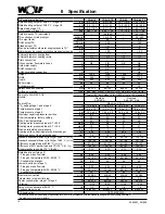
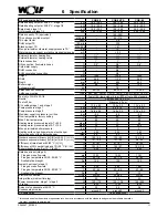
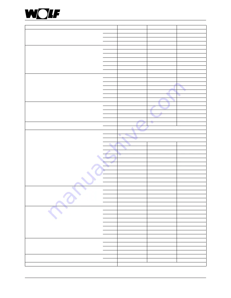
Oil condensing boilers
COB-29
COB-29/TS
COB-40
Rated heating output at 80/60 °C, stage 1/2
kW
18,5 / 28,2
18,5 / 28,2
25,3 / 38,0
Rated heating output at 50/30 °C, stage 1/2
kW
19,6 / 29,6
19,6 / 29,6
26,8 / 40,0
Rated load, stage 1/2
kW
19,0 / 29,0
19,0 / 29,0
26,0 / 38,8
Oil throughput, stage 1/2
kg/h
1,60 / 2,45
1,60 / 2,45
2,44 / 3,64
Rated capacity TS (equivalent)
l
-
160 (260)
-
TS continuous cylinder output
kW/Ltr/h
-
29 / 710
-
TS output factor
NL60
-
5.0
-
DHW output TS
l/10 min
-
300
-
Standby input TS
kWh/24 h
-
1,47
-
Max. permissible cold water supply pressure TS*
bar
-
10
-
Minimum anode current, protective magnesium anode
mA
-
> 0,3
-
External diameter, heating flow
G
1½"
1½"
1½"
External diameter, heating return
G
1½"
1½"
1½"
Drain connection
1“
1“
1“
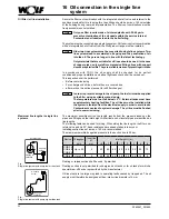
Oil connection, flow/return hoses
G
3/8“
3/8“
3/8“
Cold water supply
G
-
3/4“
-
DHW connection
G
-
3/4“
-
DHW circulation connection
G
-
3/4“
-
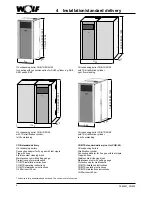
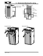
Height
mm
1290
1290
1490
Width
mm
566
1132
566
Depth
mm
605
605
605
Boiler weight
kg
99
99
122
Cylinder weight
kg
-
76
-
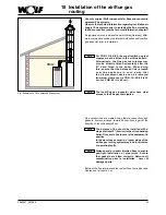
Balanced flue connection
mm
80/125
80/125
110/160
Air/flue gas routing
Type
B23, B33, C33(x), C43(x), C53(x), C63(x), C83(x), C93(x)
Fuel oil to DIN 51603-1/6
Fuel oil EL, low sulphur, bio-oil B10 or fuel oil EL standard
Nozzle *
Danfoss 0.55 / 80° S LE
Fuel oil filter
Siku max. 40 μm
CO
2
setting stage 1 and stage 2
%
13,5 ± 0,3
13,5 ± 0,3
13,5 ± 0,3
Pump pressure stage 1
bar
8,5 ± 1,0
8,5 ± 1,0
11,0 ± 1,0
Pump pressure stage 2
bar
16,8 ± 2,5
16,8 ± 2,5
23,5 ± 2,5
Maximum negative pressure in oil line
bar
-0,3
-0,3
-0,3
Flow temperature, factory setting
°C
80
80
80
Max. Flow temperature
°C
90
90
90
Heating water pressure drop at Δ T=20 K
mbar
17
17
54
Heating water pressure drop at Δ T=10 K
mbar
55
55
205
Max. permissible boiler pressure
bar
3
3
3
Heating surface, heating water heat exchanger
m²
3,05
3,05
3,85
Water capacity of the heat exchanger
litres
9.0
9.0
11,5
Standard seasonal efficiency [to DIN] at 40/30 °C (H
i
/ H
s
)
%
105 / 99
105 / 99
104 / 98
Standard seasonal efficiency [to DIN] at 75/60 °C (H
i
/ H
s
)
%
101 / 96
101 / 96
98 / 93
Efficiency at rated load at 80/60 °C (H
i
/ H
s
)
%
97 / 91
97 / 91
98 / 92
Efficiency at 30% partial load and TR=30 °C (H
i
/ H
s
)
%
103 / 97
103 / 97
103 / 98
Boiler standby loss qB at 70 °C (EnEV)
%
0,55
0,55
0,45
Rated heat input (stage 2):
Flue gas mass flow rate
g/s
13,33
13,33
17,51
Flue gas temperature 50/30 - 80/60 °C
°C
55 - 76
55 - 76
56 - 83
Available fan draught
Pa
105
105
150
Lowest heat input (stage 1):
Flue gas mass flow rate
g/s
9,05
9,05
10,91
Flue gas temperature 50/30 - 80/60 °C
°C
40 - 64
40 - 64
43 - 68
Available fan draught
Pa
55
55
72
Electrical connection
V~/Hz
230/50
230/50
230/50
Integral fuse (medium time lag)
A
5 A
5 A
5 A
Power consumption, stage 1 / stage 2
W
129 / 178
129 / 178
126 / 205
IP rating
IP 20
IP 20
IP 20
Amount of condensate at 40/30 °C
l/h
2,2
2,2
2.8
Condensate pH value
around 3
around 3
around 3
CE designation
CE-0085BS0326
* this nozzle enables the emission requirements to be met in accordance with the standard and guarantees reliable operation.
No other nozzles are permissible!
6 Specification
Summary of Contents for COB
Page 78: ...78 3062547_201802 43 Notes ...
Page 79: ...79 3062547_201802 43 Notes ...


