49
3062547_201802
31 CO
2
check/adjustment by matching
the pipe lengths
CO
2
adjustment by
matching the pipe lengths
HG 00 CO
2
adjustments
Factory setting: 3
1 2 3 4 5
Lower CO
2
value
Higher CO
2
value
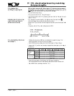
With contractor parameter HG 00 (see chapter 19 "Contractor level parameters"),
the appliances can be matched to the flue system by changing the speed for
both
stages and therefore the CO
2
value can be changed.
- Remove front and top casing.
- Remove the cap from the r.h. "flue gas" test port.
- Insert the test probe of the CO
2
measuring instrument into the "flue gas" test port
(approx. 70 mm).
- Turn the program selector switch on the BM module to "Emissions test" .
(Illuminated signal ring as status indicator flashes yellow.)
- Measure the CO
2
content and compare it against the values given in the stage 2 table
below.
- If required, alter the CO
2
content with parameter HG00.
- Modifying the parameter HG00 has also adjusted the speed for stage 1. For
checking purposes, the boiler must be set to stage 1.
- Switch HG28 burner operating mode from 2(two-stage) to 1(single stage).
- Measure the CO
2
content and compare it against the values given in the stage 1
table below.
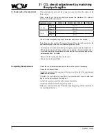
Appliance open
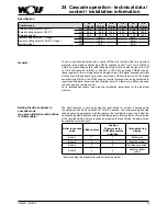
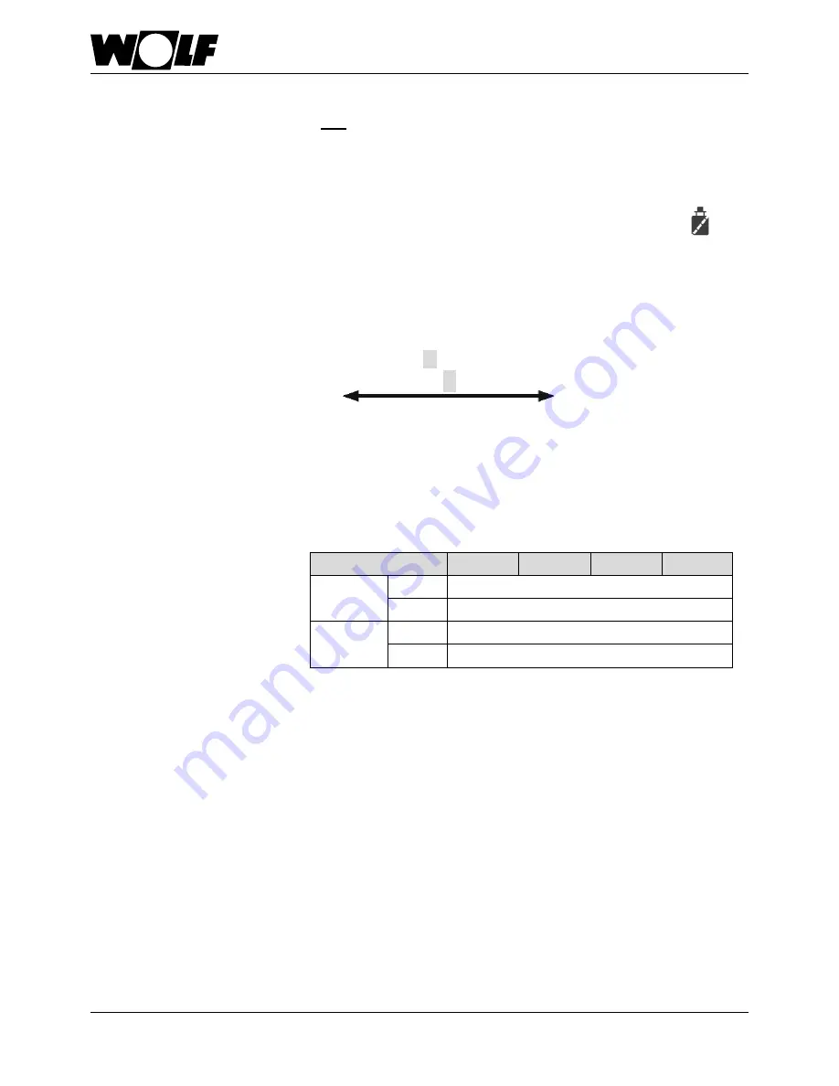
COB-15
COB-20
COB-29
COB-40
Set CO
2
value
Stage 2
12,7 ± 0,3%
Stage 1
12,7 ± 0,3%
O
2
set value
Stage 2
3,8 ± 0,4%
Stage 1
3,8 ± 0,4%
- If the value lies outside of the set value, the CO
2
-value must be set
via the pump pressure (see Commissioning without Wolf control accessories).
- Reset HG28 burner operating mode from 1 to 2.
CO
2
check/setting in the lower
load (stage 1)
Adjusting the CO
2
value in the
upper load range (stage 2)
(emissions test mode)
Summary of Contents for COB
Page 78: ...78 3062547_201802 43 Notes ...
Page 79: ...79 3062547_201802 43 Notes ...

