25
3060918_1203
Pressure jet oil burner installation /
Electrical supply
Electrical supply
Do not route sensor leads with
230 V mains cables.
Connect the heating circuit pump(s) and
the DHW cylinder loading pump(s) on-site
via contactor, if:
• The burner and pump draw more than
2 A each.
• The total control unit power consumption
is exceeded.
Observe the control unit installation and
operating instructions.
Note
Electrical supply
Cable grommets
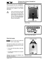
Pressure jet oil burner installation
The Unit pressure jet oil burner installation
instructions are included in the burner
packaging.
Only use bolts when securing
the burner to the boiler flange,
whose thread penetrates the
boiler flange by a maximum of
15 mm. Only use pressure jet
gas burners compliant with EC
Directive 90/396/EEC.
Boiler flange
Burner flange holes
1
N
T1 T2 S3 B4
BS
MV
Burner plug wiring diagram


