Page 12
Installation Information
Gas Cooktop (CTG) Series
Gas Cooktop (CTG) Series
2-7
#802985 - Revision E - August, 2011
FILLER STRIP INSTALLATIONPROCEDURE
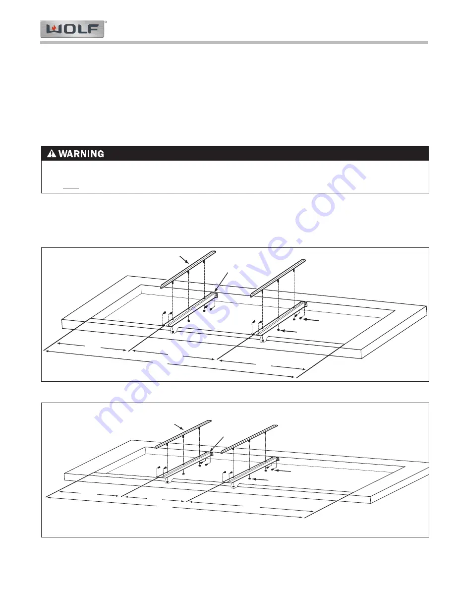
(Refer to Figures 2-12 & 2-13 Below)
These instructions contain procedural information to install the Integrated Filler Strip Kit into countertop installations.
1.
Locate the center of the Filler Strip Bracket (2) at the required distance from the cooktop cutout edge.
2.
Position the Filler Strip Bracket (2) so that the top surface is flush with the counter top. You may need a straight
edge to assist in locating the bracket at the correct height.
3.
Mark the center of the elongated slots of the Filler Strip Bracket (2) on the front and rear of the cooktop cutout.
4.
Using a 3/32" drill bit, drill a ¾" deep pilot hole for the #6/32 (3) mounting screws.
5.
Secure the Filler Strip Bracket (2) to the counter top.
14
5/8"
44
1/2"
15
1/4"
3
4
1
2
14
5/8"
Figure 2-13. Filler Strip with Two Integrated Cooktops and a 30" Gas or Electric Cooktop, Typical Installation
14
5/8"
59
1/2"
15
1/4"
29
5/8"
1
2
3
4
Figure 2-12. Filler Strip with Three Integrated Cooktops, Typical Installation.
PLEASE CONSULT WITH THE COUNTERTOP MANUFACTURER/INSTALLER FOR PROPER METHOD OF
INSTALLING SCREWS INTO INSIDE EDGE OF COUNTERTOP. DAMAGE MAY OCCUR IF PROPER METHODS
ARE NOT USED.
6.
Install all cooktops into the corresponding openings.
7.
Position the Filler Strip (1) into the Filler Strip Bracket (2) and install the three #10-24 nuts (4), but do not tighten.
8.
Align and adjust cooktops and filler strips in the countertop opening and then tighten cooktop hold down clamps
and filler strip nuts.


