D
Du
ua
all F
Fu
ue
ell R
Ra
an
ng
ge
e
Operation Information
3-20
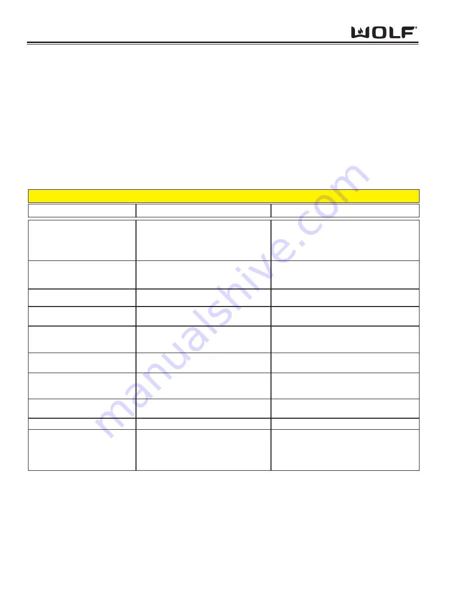
ERROR INDICATORS
Error codes can give a visual and audible alarm. The visual indication will be “Err” displayed in the Cook Time digits
and the number or letter of the error code will be displayed in the Stop Time digits of the Electronic Control Housing.
The Oven Temperature Readout Knob will also show “Err” in the display window. The last seven errors will be
stored in the EEPROM for recall when in diagnostic mode.
ERROR CODE
POSSIBLE CAUSE
TEST / ACTION
ERROR CODE CHART
Figure 3-65. Error Code Chart
01
02
03
04
07
08
09
0B
0C
0E
Door Lock or Unlock Switches not sensed
within 60 seconds while driving the door
lock motor
Over temperature occurs when the oven
reaches a temperature of 630 °F for an
unlocked door and 950°F for a locked door
Open circuit detected on RTD Oven Sensor
Shorted circuit detected on the RTD Sensor
SPI Communication lost from ECH to the
Control Board as reported by Control Board
EEPROM checksum is incorrect. Checked
at power up
Meat probe being sensed as shorted
Analog to Digital error during calibration
phase
Communication lost with oven controller
Power relay shorted, sensed as closed
when should be open
Failure of element circuit
Failure of relay drive circuitry
Perform motorized door lock test procedure in
diagnostic mode
Ohm door lock switches. Replace MDL (Motor
Door Lock) Assembly if defective
Ohm RTD sensor, replace if defective. If RTD
good replace oven controller.
Ohm RTD sensor, replace if defective. If RTD
good replace oven controller.
Ohm RTD sensor, replace if defective. If RTD
good replace oven controller.
Code reflects that the ECH cannot fine the
Control Board. Replace cable first. Replace
ECH if replacing cable does not correct problem
Replace oven controller
Initiated diagnostic mode and check meat
probe. Ohm meat probe, check reading with
Tech Data
Replace oven controller
Replace oven controller
Replace relay board
Replace relay board
Replace relay board
Summary of Contents for DF304
Page 2: ......
Page 12: ...D Du ua al l F Fu ue el l R Ra an ng ge e General Information 1 10 ...
Page 62: ...4 22 Component Access Removal D Du ua al l F Fu ue el l R Ra an ng ge e ...
Page 77: ...Technical Data D Du ua al l F Fu ue el l R Ra an ng ge e 6 1 SECTION 6 TECHNICAL DATA ...
Page 81: ...Wiring Diagrams D Du ua al l F Fu ue el l R Ra an ng ge es s 7 1 WIRING DIAGRAMS SECTIO N 7 ...


