Component Access & Removal
4-11
D
Du
ua
all F
Fu
ue
ell R
Ra
an
ng
ge
e
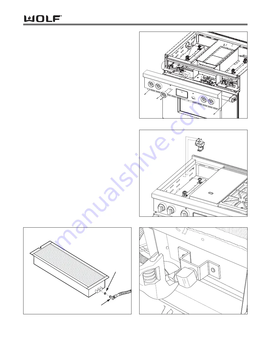
Figure 4-22. Solenoid Removal
Figure 4-21. Thermostat Removal
Figure 4-23. Infrared Burner Gas Line Removal
Infrared Thermostat Removal
The griddle thermostat is mounted to the bull nose with
two screws and the thermostat bulb is inserted into a
channel on the support assembly beneath the griddle
plate.
To remove the thermostat, first lift off the griddle plate
and slide the thermostat bulb from the support assem-
bly. Pull the griddle knob from the shaft of the thermo-
stat and extract the thermostat mounting screws.
Remove the bull nose from the unit
(See Bull Nose
Removal Instructions).
Unplug the electrical leads from
the thermostat. (See Figure 4-21)
Solenoid Removal
The griddle solenoid valve is mounted to the side wall
beneath the burner pan, usually on the left hand side.
In order to remove the solenoid, the surface burner
components will need to be removed first. Extract the
solenoid cover mounting screws and remove the cover.
Disconnect the gas lines from the solenoid. Now,
extract the screws from the solenoid mounting bracket
and pull the solenoid from the unit. (See Figure 4-22)
IR Orifice Removal
The orifice is located in the brass orifice elbow, which is
threaded into the orifice holder at the front of the IR
burner. The Ir weld assembly must be raised up and
placed on the ECH shield for access.
To remove the orifice, first disconnect the gas line from
the brass orifice elbow. Then, unscrew the elbow from
the orifice holder and extract the orifice from the elbow
with wrenches. (See Figure 4-20 and 4-23)
Figure 4-20. IR Charbroiler Orifice Removal
IR Charbroiler
Orifice
Orifice Elbow
Summary of Contents for DF304
Page 2: ......
Page 12: ...D Du ua al l F Fu ue el l R Ra an ng ge e General Information 1 10 ...
Page 62: ...4 22 Component Access Removal D Du ua al l F Fu ue el l R Ra an ng ge e ...
Page 77: ...Technical Data D Du ua al l F Fu ue el l R Ra an ng ge e 6 1 SECTION 6 TECHNICAL DATA ...
Page 81: ...Wiring Diagrams D Du ua al l F Fu ue el l R Ra an ng ge es s 7 1 WIRING DIAGRAMS SECTIO N 7 ...


