D
Du
ua
all F
Fu
ue
ell R
Ra
an
ng
ge
e
Component Access & Removal
4-18
When removing or disconnecting the door hinge, remember it could recoil quickly when released.
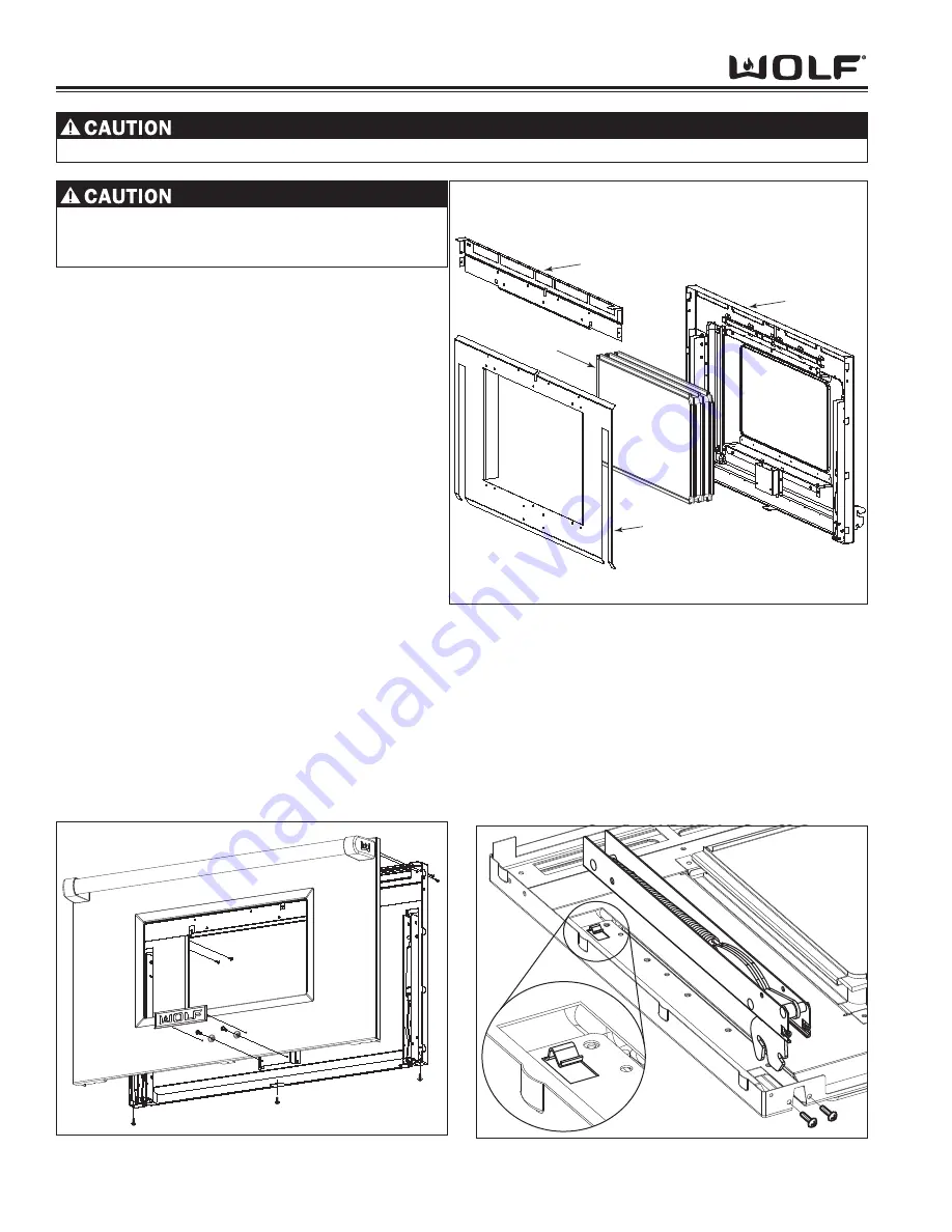
Figure 4-40. Spring and Hydraulic Hinge Removal
Figure 4-39. Glass Pack Assembly Removal
Door Liner Bracket
Glass Pack
Assembly
Door Liner
Door Baffle
Outer Door Skin Assembly Removal
First, remove the oven door assembly and lay on front.
Extract the two screws on the inside top of the door
liner. Next, extract the three screws at the bottom of
the outer door skin. Then, remove the outer door skin
with handle and lay on front. Now, extract the four
screws from the door handle assembly and remove.
Remove the heat shield and insulation from the outer
door skin. (See Figure 4-38).
Glass Pack Removal
To begin, remove the oven door assembly. Then
remove the outer door skin. Now, extract the screws
that secure the door liner bracket to the door liner, also
extract the screws on the sides of the door liner bracket
in order to remove. Now, remove door baffle from
around glass pack. Now, lift the glass pack up and
remove. (See Figure 4-39)
Hinge Removal
To begin, remove the oven door assembly and outer
door skin assembly. Next, extract the two screws at the
bottom corner of the door liner. Raise the bottom of the
door hinge assembly from the door liner. Then, using a
small flat bladed screwdriver, carefully raise the tab at
the top of the hinge and slide the hinge out from under
tab and remove. (See Figure 4-40)
Figure 4-38. Door Skin Removal
Hydraulic Hinge Removal
To begin, remove the oven door assembly and outer
door skin assembly. Next, extract the two screws at the
bottom corner of the door liner. Now, raise the bottom
of the hydraulic hinge assembly from the door liner.
Then, using a small flat bladed screwdriver carefully
raise the tab at the top of the hydraulic hinge and slide
the hinge out from under tab and remove. (See Figure
4-40)
Logo must be removed prior to disassembly of
door. Use of a heat gun and putty knife, wrapped
with tape, will help in the removal.
Summary of Contents for DF304
Page 2: ......
Page 12: ...D Du ua al l F Fu ue el l R Ra an ng ge e General Information 1 10 ...
Page 62: ...4 22 Component Access Removal D Du ua al l F Fu ue el l R Ra an ng ge e ...
Page 77: ...Technical Data D Du ua al l F Fu ue el l R Ra an ng ge e 6 1 SECTION 6 TECHNICAL DATA ...
Page 81: ...Wiring Diagrams D Du ua al l F Fu ue el l R Ra an ng ge es s 7 1 WIRING DIAGRAMS SECTIO N 7 ...


