


Install the Switch Mode Power Supply
1
Place the switch mode power supply on to the control
board supports.
2
Connect the wire connectors and wire harness to the switch
mode power supply.
FAN ASSEMBLY REMOVAL
WARNING
Disconnect the product from the power source
before starting this procedure.
To remove the fan assembly, first
remove:
1
2
3
4
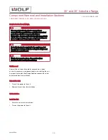
Remove the Fan Assembly
1
Disconnect the fan assembly wire harness.
2
Use a small flat-blade screwdriver to spread the fan
assembly retainer tabs to release the fan assembly.
3
Remove the fan assembly from the generator.
FAN ASSEMBLY INSTALLATION
After installing the fan assembly, install:
1
2
3
4
.
Install the Fan Assembly
1
Press the fan assembly into the fan assembly retainer tabs.
2
Connect the fan assembly wire harness to the generator.
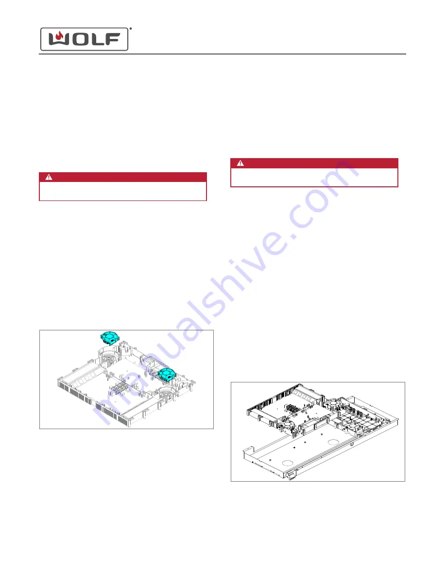
GENERATOR ASSEMBLY REMOVAL
WARNING
Disconnect the product from the power source
before starting this procedure.
To remove the generator assembly, first
remove:
1
2
3
4
Remove the Three-Burner or Four-Burner Generator Assembly
1
Remove the wire harness connector from the generator
support.
2
If there is a two-burner generator assembly, disconnect the
wire connectors and wire harnesses from the three-burner
or four-burner generator assembly.
3
Turn the three-burner or four-burner generator assembly
over.
4
Use a T-20 Torx bit or flat-blade screwdriver to loosen the
terminal block screws. Disconnect the power wire
connectors.
5
Remove the three-burner or four-burner generator assembly
from the generator support.
Remove the Two-Burner Generator Assembly
1
Disconnect the wire connectors and wire harness from the
two-burner generator assembly.
30" and 36" Induction Range
Cooktop Component Removal and Installation
Install the Switch Mode Power Supply (continued)
service.subzero.com
829191 REVA
49


