background image

Induction Range (IR) Series

Induction Range (IR) Series

Component Removal

3-4

#827176 - Revision A.1 - December, 2016

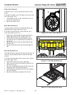
Door Skin Removal

The door skin and handle are attached to the liner
assembly by two screws below the logo, three screws
on the bottom of the door, and four screws at the top of
the liner assembly.

To remove the door skin, first remove the door, then
(See Figure 3-4):

Place tape around the logo and use a putty knife to

1

peal the logo from the front of the door.
Extract the screws behind the logo.

2

Extract the screws from the bottom of the door.

3

Extract the screws from the top of the liner assem-

4

bly.
Lift the door skin from the liner assembly.

5

Hinge Removal

The hinges are attached to the liner assembly by two
screws at the bottom of the liner assembly, and a tab
on the liner assembly at the top of the hinge.

To remove a hinge, first remove the door skin, then
(See Figure 3-5):

Extract the screws at bottom of the liner assembly. 

1

Lift the bottom of the hinge up past the edge of the

2

liner and disengage the hinge from the tab.
Remove the hinge from the liner assembly.

3

Glass Pack Assembly Removal

The glass pack is inserted into the liner assembly and
has insulation and brackets around it to keep it in place.

To remove the glass pack assembly, first remove the
door skin, then  (See Figure 3-6):

Extract screws from reinforcement bracket and

1

remove the reinforcement bracket.
Extract the screws from the four glass pack retainer

2

brackets, and remove them.
Extract the screws from the door baffle and remove

3

the door baffle.
Remove the glass pack.

4

Figure 3-5.  Hinge Removal

Tab for Hinge

Figure 3-6.  Glass Pack Removal

Reinforcement
Bracket

Glass Pack
Retainer Brackets

Door Baffle

Glass Pack

Figure 3-4.  Door Skin Removal

Summary of Contents for Induction Range Series

Page 1: ...ts from a Wolf appliance take note of the WARN INGS and CAUTIONS below TO AVOID ELECTRIC SHOCK POWER TO THE UNIT MUST BE DISCONNECTED WHENEVER SERVICING AND OR ACCESSING COMPONENTS KEEP IN MIND THAT U...

Page 2: ...ide of the oven door changing the space between the top of the oven door and the bullnose To adjust the oven door See Figure 3 2 Remove the unit skirt 1 Use a 5 32 allen wrench to adjust the screw 2 C...

Page 3: ...and a tab on the liner assembly at the top of the hinge To remove a hinge first remove the door skin then See Figure 3 5 Extract the screws at bottom of the liner assembly 1 Lift the bottom of the hin...

Page 4: ...ers to compress the spring pins 1 on the back of the gasket Remove the gasket 2 Rack Removal There are three types of racks in the oven The flat rack which can be used in any position in the oven the...

Page 5: ...all with screws To remove the convection baffle first remove the rack guides then See Figure 3 11 Extract the screws above and below the convection 1 baffle Remove the convection baffle from the oven...

Page 6: ...fan 3 Remove the fan from the oven 4 Temperature Sensor Removal The temperature sensor is attached to the back wall of the oven To remove the temperature sensor first remove the oven racks then See Fi...

Page 7: ...he broil element and broil deflector pan for 2 ward into the oven and disconnect the electrical connectors Remove the broil element and broil deflector pan 3 from the oven Remove the broil element fro...

Page 8: ...ack of the island 1 trim Remove the island trim 2 Extract the two outer screws from the rear of the 3 cooktop Lift the cooktop from the rear disengaging the front 4 of the cooktop from the keyhole slo...

Page 9: ...ss from the ECH 5 Remove the bullnose 6 Side Panel Removal The side panels are attached to the front and back of the unit with the induction cooktop resting on top of them To remove a side panel first...

Page 10: ...TCO convection fan connec tions terminal block wire harnesses and cooling fan cover To remove the back panel See Figure 3 25 Extract the far left and far right screws from the 1 island trim Extract t...

Page 11: ...ving the access cover Replacing the terminal block requires the unit to be pulled from the installation To remove the terminal block first remove the back panel then See Figure 3 28 Disconnect the wir...

Page 12: ...th rivets 2 Use a phillips screw driver to extract the shoulder 3 screws from the front frame See Figure 3 31 Use a T 20 Torx bit to extract the screws from the 4 sides and back Remove the glass top 5...

Page 13: ...d by insulation The black insulation is on the solid black wire and should be connected to the coil assembly terminal near est the front Generator Plate Removal To remove the generator plate first dis...

Page 14: ...large flat blade 1 screw driver to disconnect power wire harness Disconnect comm cable 2 Remove generator assembly 3 Generator Assembly Removal IR365 To remove the generator assembly first remove the...

Reviews: