19
3062880_0910
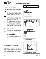
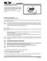
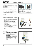
Fig.: Connection, heating circuit pump
Heating circuit pump connection (230 V AC; max.
400 VA)
Insert the cable glands into the terminal box. Insert
and secure the cable through the cable entry.
Connect the heating circuit pump 230 V AC to terminals
L1, N and
.
Electrical connection
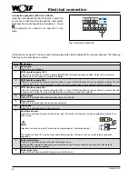
Wiring diagram, ventilation air damper
(not for MGK-130)
Schaltplan für
Zuluftklappe
MGK 170-250
1
von 1
AF
E1
eBUS
+
-
1 2
a b
Netz
Z
A1
N
N
N
L1
L1
L1
o o o o o o
MT
3,15 A
F1
1 2
1 2
1 2
L1
N
L1
L1
N
N
L1
N
L1
N
Supply air damper
with servomotor
Elektroanschlußkasten
MGK
24VDC
Limit switch
NB:
Limit switch for supply air damper must
be floating!
Otherwise the MGK control unit will be
destroyed.
Note:
The contractor parameter
(input 1)
(factory setting for supply air damper) and
(input 1)
(factory setting for supply air damper)
With the contact open, the burner remains
blocked for DHW and central heating, even
for emissions test and frost protection.
HG13/GB13
must be set to 5
HG14/GB14
must be set to 7
Power supply
230 V AC
br
bl
M
230V~
51-10-018-045
Benennung
Zeichnungsnummer
CorelDraw
Art.- / Materialnummer
Blatt
Bl.
Name
Name Ausg.
Ausg.
Änderung
Änderung
Antrag
Antrag
Datum
Datum
Terminal box MGK
5 A

