46
3063772_201507
25. Parameter description
Important information:
In these schematic diagrams, shut-off valves, air vent valves and safety equipment are not fully represented. These should be
provided in compliance with the applicable standards and regulations for each individual system.
Hydraulic and electrical details can be found in the Hydraulic System Solutions technical guide.
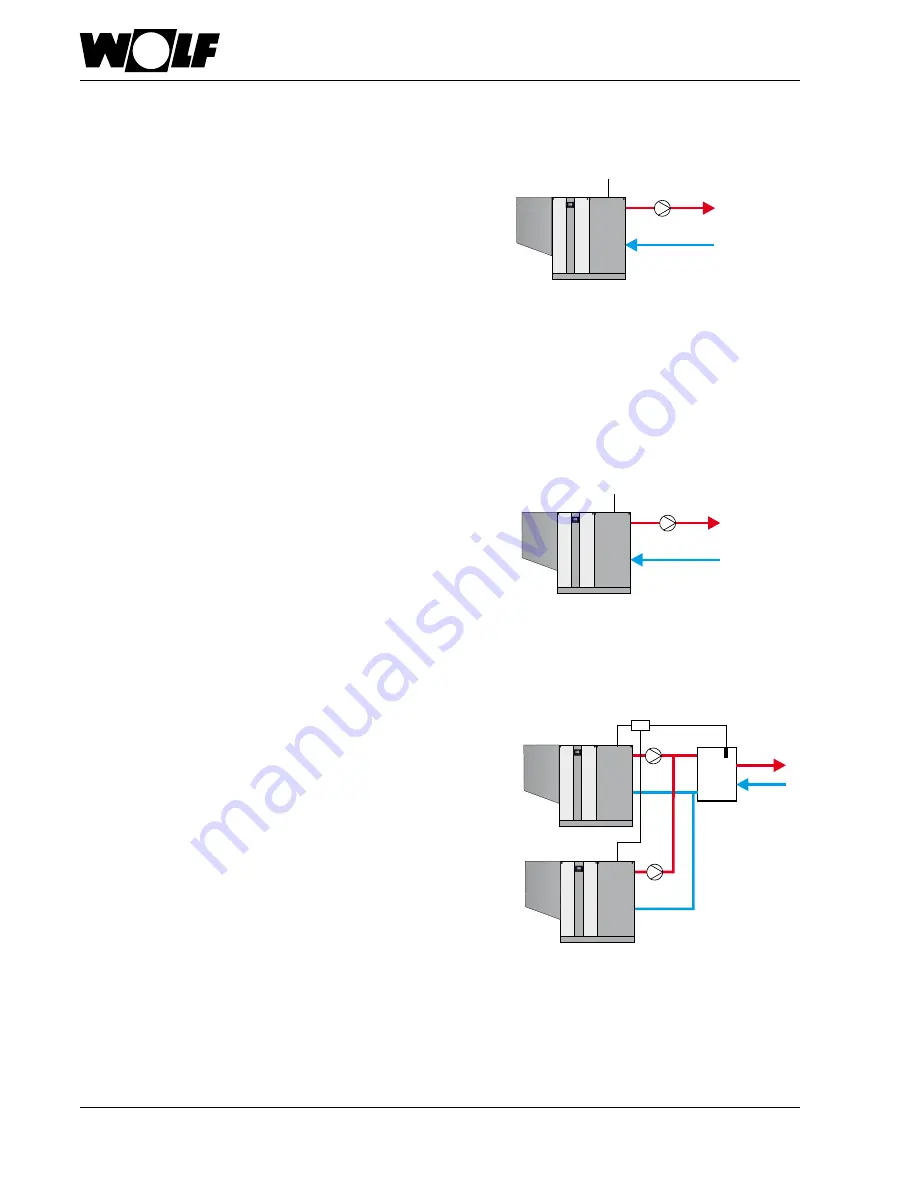
System configuration 51
BMS burner output
E2
BMS%
ZHP
Burner is activated subject to demand from the external controller
•
Feed/heating circuit pump (ZHP)
activated as feed pump from 2 V upwards
•
No temperature control
•
Input E2:
Control 0-10 V by external controller
0-2 V burner OFF,
2-10 V burner output min. to max. within the programmed limits
(HG02 and HG04)
•
Automatic output reduction when approaching TK
max
(HG22) is
activated. Deactivation on reaching TK
max
Note:
If the pressure drop of the boiler incl. the pipework is
> 700 mbar, a low loss header must be installed.
System configuration 52
BMS set boiler temperature
ZHP
E2
BMS°C
•
Burner is activated subject to demand from the boiler
thermostat
•
Feed/heating circuit pump (ZHP)
activated as feed pump from 2 V upwards
•
Boiler thermostat
•
Input E2:
Control by external controller with 0-10 V
0-2 V burner OFF
2-10 V set boiler temperature TK
min
(HG21) - TK
max
(HG22)
Note:
If the pressure drop of the boiler incl. the pipework is
> 700 mbar, a low loss header must be installed.
System configuration 60
Cascade for multi boiler systems (setting automatic when
cascade module is connected)
•
Burner is activated subject to demand from cascade module
via eBUS (0-100 % burner output; min. to max. within the
programmed limits) (HG02 and HG04)
•
Feed/heating circuit pump (ZHP) activated as feed pump
•
Header temperature control via cascade module
•
Input E2: not assigned
•
Automatic output reduction when approaching TK
max
(HG22)
is activated. Deactivation on reaching TK
max
• A low loss header or plate heat exchanger can be used as
system separation.
ZHP
SAF
eBUS
KM
eBUS
ZHP


