background image

OV E N D O O R  

R E M O V A L

12

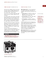
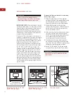
Place Hinge Pin on

Spring Hinge Side of Door

Place Hinge Pins on

Spring Hinge Side of Door

Spring hinge location for 30" (762)
and 36" (914) gas ranges

Spring hinge locations for 48" (1219)
and 60" (1524) gas ranges

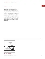
Hinge 

Retainer 

Plate 

Upper Mounting 

Screw 

Hinge 

Pin 

Kickplate 

Oven door removal

IMPORTANT NOTE: The oven door(s) should
not be removed unless it is necessary to fit the
range through a tight doorway. Door removal
should only be done by a qualified service
technician or installer. Door removal and rein-
stallation may cause damage to the porcelain
interior of the oven or door(s).

If removal of the oven door(s) is necessary, a
hinge pin, supplied with the range, will need to
be inserted in the appropriate hinge arm. For
each oven door, only one hinge arm is spring
loaded, requiring use of the hinge pin for
removal of the oven door. The hinge pin will
be found taped to the inside of the oven door. 

For 30" (762) and 36" (914) gas ranges, the
hinge pin will be inserted through the hole in
the right hinge arm (facing the unit). On 48"
(1219) and 60" (1524) gas ranges, the spring
hinges are located on the outer edges of the
unit. On these units, the left oven door will
have the spring hinge on the left side and the
right oven door will have the spring hinge on
the right side. Refer to the illustrations below
for the location of the spring hinge(s) for your
specific model.

If removal of the oven door(s) is necessary,
follow these steps:

1)

Open the oven door to its fully opened
position and insert the supplied door hinge
pin through the hole in the appropriate
hinge arm. Refer to the illustration below.

2)

Remove both upper and lower hinge
retainer mounting screws. NOTE: The oven
gasket may have to be moved slightly to
access the bottom screws.

3)

After removing the mounting screws, move
the hinge retainer plate forward slightly.
NOTE: The hinge retainer plate will remain
on the door hinge assembly after the
mounting screws have been removed.

4)

Carefully close the oven door to about a
60° angle from horizontal and lift the door
away from the oven. NOTE: A slight racking
motion may be required for removal.

5)

For 48" (1219) and 60" (1524) gas ranges,
complete these steps for both oven doors.

Do not lift or carry the oven door by the
door handle. 

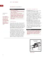
Failure to insert the hinge pin in the
appropriate hinge arm will cause damage
to the range. Minor injuries may occur.

W O L F  

G A S   R A N G E S

Summary of Contents for R304LP

Page 1: ...INSTALLATION INSTRUCTIONS G A S R A N G E S...

Page 2: ...ould like to identify is IMPORTANT NOTE This highlights informa tion that is especially relevant to a problem free installation signals a situation where minor injury or product damage may occur if yo...

Page 3: ...der the drip pan that supports the cooking grates on the left inside wall of the range Refer to the illustration below The rating plate for Model R482CF is located on the right inside wall W O L F GAS...

Page 4: ...trong draft areas such as windows doors and strong heating vents or fans Do not obstruct the flow of air The area in which you are installing this appliance must have an adequate supply of fresh air t...

Page 5: ...nd insulated homes A qualified HVAC contractor should be consulted A C C E S S O R I E S Optional acces sories are available through your Wolf dealer To obtain local dealer information visit the Locat...

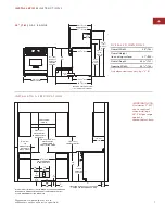
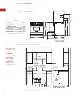
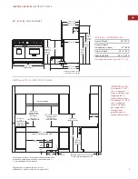
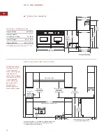
Page 6: ...illustrations for your model on pages 7 10 for the exact rough opening dimensions WA L L I N S TA L L AT I O N S Minimum clearances to combustible surfaces A minimum clearance of 18 457 must be maint...

Page 7: ...in 457 TO COUNTERTOP 37 940 TO COOKING SURFACE 13 max 330 6 min 152 TO COMBUSTIBLE MATERIALS BOTH SIDES 30 762 OVERALL WIDTH 36 914 37 940 OVERALL HEIGHT TO COOKING SURFACE 21 2 64 241 2 622 251 4 641...

Page 8: ...LS BOTH SIDES 36 914 OVERALL WIDTH 36 914 37 940 OVERALL HEIGHT TO COOKING SURFACE 21 2 64 241 2 622 251 4 641 LEGS AND CASTERS ALLOW 1 25 HEIGHT ADJUSTMENT 433 8 1102 463 4 1187 WITH 10 RISER 563 4 1...

Page 9: ...13 max 330 6 min 152 TO COMBUSTIBLE MATERIALS BOTH SIDES 48 1219 OVERALL WIDTH 36 914 37 940 OVERALL HEIGHT TO COOKING SURFACE 21 2 64 241 2 622 251 4 641 LEGS AND CASTERS ALLOW 1 25 HEIGHT ADJUSTMENT...

Page 10: ...60 1524 OVERALL WIDTH 36 914 37 940 OVERALL HEIGHT TO COOKING SURFACE 21 2 64 241 2 622 251 4 641 LEGS AND CASTERS ALLOW 1 25 HEIGHT ADJUSTMENT 433 8 1102 463 4 1187 WITH 10 RISER 563 4 1441 WITH 20 R...

Page 11: ...WALL FLOOR 61 2 165mm MIN TO FLOOR SIDE PANEL ANTI TIP BRACKET REAR CHANNEL BRACE Anti tip bracket installation This range can tip Injury to persons could result Install the anti tip bracket packed w...

Page 12: ...ges are located on the outer edges of the unit On these units the left oven door will have the spring hinge on the left side and the right oven door will have the spring hinge on the right side Refer...

Page 13: ...ange The 3 76 front legs are adjusted by rotating the bottom hexagonal portion of the leg The rear casters can be adjusted by rotating the 25 16 59 nut on the caster The range legs and casters allow f...

Page 14: ...olumn 5 psi 3 5 kPa Failure to do so can result in explosion fire or death W O L F GAS RANGES Gas Supply Line To Appliance SHUT OFF VALVE Open Position Shut off valve I M P O RTA N T N OT E This insta...

Page 15: ...WC water column A natural gas pressure regulator is installed For Propane LP Gas Standard orifices are set for 10 25 mb WC water column A propane gas pressure regulator is installed Gas Supply Pressu...

Page 16: ...and ordinances when installing your service R E C O M M E N D E D G RO U N D M E T H O D IMPORTANT NOTE This appliance must be properly grounded to avoid shock hazard The range is equipped with a 3 pr...

Page 17: ...llation may cause damage to the porcelain interior of the oven or door s If the oven door s have been removed as described on page 12 follow these steps to reinstall 1 Hold the oven door on both sides...

Page 18: ...tinues until the electronic ignition senses a flame Be sure to place the burner parts on each burner base and install the burner grates before lighting To check operation of the surface burners push i...

Page 19: ...Customer Service at 800 332 9513 When calling for service you will need the model and serial numbers of the gas range Both numbers are listed on the product rating plate located under the drip pan th...

Page 20: ...8 0 7 5 8 2 R E V B 1 0 2 0 0 6 WOLF APPLIANCE COMPANY INC P O BOX 44848 MADISON WI 53744 800 332 9513 WOLFAPPLIANCE COM...

Reviews: