15
Dimensions in parentheses are in
millimeters unless otherwise specified.
I N S TA L L AT I O N
I N S T R U C T I O N S
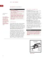
G A S L E A K T E S T I N G
Use a brush and liquid detergent to test all gas
connections for leaks. Bubbles around connec-
tions will indicate a leak. If a leak appears, shut
off the gas valve and adjust connections. Then
check connections again. Clean all the deter-
gent solution from the range.
Never test for a gas leak with a match or
other flame.
G A S S U P P LY
R E Q U I R E M E N T S
G A S M A N I F O L D P R E S S U R E
For Natural Gas: Standard orifices
are set for 5" (12.5 mb) WC (water column).
A natural gas pressure regulator is
installed.
For Propane (LP) Gas: Standard orifices
are set for 10" (25 mb) WC (water column).
A propane gas pressure regulator is
installed.
Gas Supply Pressure: For checking the
regulator setting, the maximum line
pressure for natural and propane (LP) gas:
14" (34.9 mb) WC; .5 psi (3.5 kPa). Minimum
line pressure for natural gas: 7" (17.5 mb)
WC. Minimum line pressure for propane
(LP) gas: 11" (27.4 mb) WC.
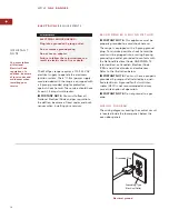
Gas Supply Regulator: To control and
maintain a uniform gas pressure in the gas
manifold, the unit must be used with a gas
pressure regulator. The burner orifices, etc.
are sized for the gas pressure delivered by
the supplied regulator. Do not remove the
regulator.
The maximum gas supply pressure to
the regulator should never exceed 14"
(34.9 mb) WC; .5 psi (3.5 kPa).

