Component Access & Removal
4-11
RANGES &
& R
RANGETOPS
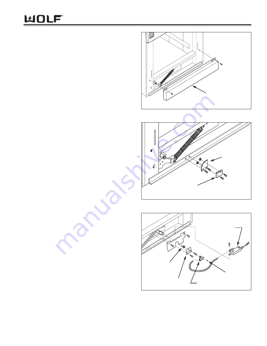
Components Behind Lower Access Panel:
Lower Access Panel Removal
The lower access panel can be removed by extracting
the mounting screws from the right and left corners of
the panel and pulling the panel forward.
(See Figure 3-26)
Door Switch Removal
The door switch is attached to a bracket with nuts and
bolts. The bracket is then attached to the bottom frame
brace with screws.
Begin removing the door switch by disconnecting the
electrical leads. Then, extract the switch bracket
mounting screws and pull the switch and bracket away
from the unit. The switch can now be removed from the
bracket by extracting the bolts from the nuts. (See
Figure 3-27)
Oven Burner Bi-Metal Valve Removal
The oven burner bi-metal valve is attached to the bot-
tom frame brace with a screw.
To remove the oven burner bi-metal valve, first discon-
nect the electrical leads and the gas lines. Then,
extract the mounting screw and lift the bi-metal valve
from the appliance. (See Figure 3-28)
Oven Burner Orifice Removal
The oven orifice is bell shaped with a hex shaped end.
One end of the oven orifice elbow is inserted through a
hole in the orifice fitting bracket. The orifice is then
threaded onto the end of the elbow that protrudes
through the bracket.
To remove the oven orifice, first remove the screws that
hold the orifice fitting bracket to the bottom frame brace.
Then, use wrenches to disconnect the oven orifice from
the orifice elbow. (See Figure 3-28)
Figure 3-26. Lower Access Panel Removal
Lower Access Panel
Figure 3-27. Door Switch Removal
Bracket
Switch
Figure 3-28. Oven Bi-Metal Valve
and Oven Orifice Removal
Orifice Fitting
Bracket
Oven Orifice
Orifice Elbow
Pipe Plug
Bi-Metal Valve
Summary of Contents for RT362F
Page 2: ......
Page 3: ...General Information RANGES R RANGETOPS 1 1 SECTION 1 GENERAL INFORMATION ...
Page 13: ...Theory of Operation 2 1 RANGES R RANGETOPS SECTION 2 THEORY OF OPERATION ...
Page 20: ...RANGES R RANGETOPS Theory of Operation 2 8 ...
Page 21: ...Installation Information RANGES R RANGETOPS 3 1 SECTION 3 INSTALLATION INFORMATION ...
Page 26: ...RANGES R RANGETOPS Installation Information 3 6 ...
Page 27: ...Component Access Removal 4 1 RANGES R RANGETOPS SECTION 4 COMPONENT ACCESS AND REMOVAL ...
Page 43: ...Troubleshooting Guide 5 1 RANGES R RANGETOPS SECTION 5 TROUBLESHOOTING GUIDE ...
Page 53: ...Technical Data 6 1 RANGES R RANGETOPS SECTION 6 TECHNICAL DATA ...
Page 56: ...RANGES R RANGETOPS Technical Data 6 4 ...
Page 57: ...R RA AN NG GE ES S R RA AN NG GE ET TO OP PS S Wiring Diagrams 7 1 WIRING DIAGRAMS SECTIO N 7 ...
Page 88: ...R RA AN NG GE ES S R RA AN NG GE ET TO OP PS S 7 32 Wiring Diagrams ...


