background image

8

3062165_201508

Information regarding the system hydraulics

All details are recommendations and may vary from system to system.


The expansion vessel sizes stated are valid for a static 

head of up to 10 metres only.

Information regarding 

the system hydraulics

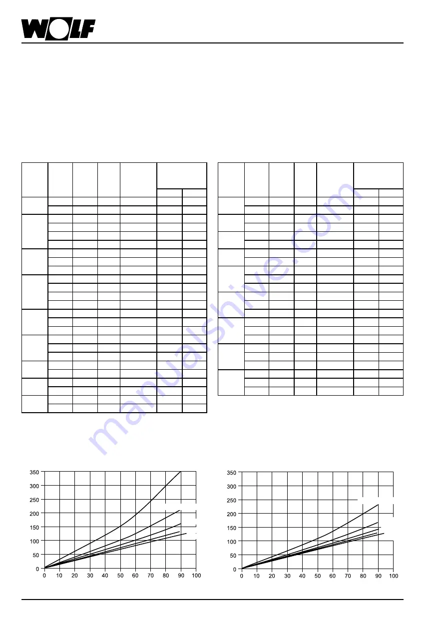
•  The collectors can be operated with a high specific flow rate (so-called  

High-Flow). Advantages: The collector is well cooled = high collector efficiency 

level, low heat losses at the flow line. Disadvantages: High pressure drop 

= powerful pump, large pipe cross-sections.

•  The  collectors  can  be  operated  with  a  low  specific  flow  rate  (so-called  

Low-Flow). Here, the advantages and disadvantages are reversed compared  

to the High-Flow operation. An additional advantage, due to the higher flow 

temperature, is the effective operation of a stratification cylinder.

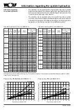
Flow data: High-Flow (90 l/h x coll), ANRO 30 °C

Flow data: Low-Flow (50 l/h x coll), ANRO 30 °C

Collector 

number

Solar 

line 

length 

(m)

Solar 

pipe Ø 

(mm)

Pump 

group

DHW 

cylinder

Expansion vessel 

2.5 bar

F3-1        F3-Q

2
2

15

15 x 1

10

SEM-2-300

18

18

30

18 x 1

10

SEM-2-300

18

18

3
3
3
3

10

15 x 1

10

SEM-2-400

25

35

20

18 x 1

10

SEM-2-400

35

35

30

15 x 1

20

SEM-2-400

25

35

70

18 x 1

20

SEM-2-400

35

35

4
4
4

15

18 x 1

10

SEM-1-500

35

50

30

22 x 1

10

SEM-1-500

50

50

50

18 x 1

20

SEM-1-500

35

50

5
5
5
5

10

18 x 1

10

SEM-1-750

50

50

20

22 x 1

10

SEM-1-750

50

50

35

18 x 1

20

SEM-1-750

50

50

90

22 x 1

20

SEM-1-750

50

50

6
6
6

15

22 x 1

10

SEM-1-750

80

80

30

18 x 1

20

SEM-1-750

50

80

70

18 x 1

20

SEM-1-750

50

80

7
7
7

15

28 x 1.5

10

SEM-1-1000

80

80

15

18 x 1

20

SEM-1-1000

80

80

50

22 x 1

20

SEM-1-1000

80

80

8
8

50

22 x 1

20

SEM-1-1000

80

80

100

28 x 1.5

20

SEM-1-1000

80

105

9
9

20

22 x 1

20

SEM-1-1000

80

80

80

28 x 1.5

20

SEM-1-1000

80

105

10
10

10

22 x 1

20

SEM-1-1000

80

105

50

28 x 1.5

20

SEM-1-1000

105

105

Collector 

number

Solar 

line 

length 

(m)

Solar 

pipe Ø 

(mm)

Pump 

group

DHW 

cylinder

Expansion vessel 

2.5 bar

F3-1        F3-Q

2
2

20

12 x 1

10

SEM-2-300

18

18

50

15 x 1

10

SEM-2-300

18

18

3
3

35

15 x 1

10

SEM-2-400

25

35

80

18 x 1

10

SEM-2-400

35

35

4
4

25

15 x 1

10

SEM-1-500

35

35

50

18 x 1

10

SEM-2-400

35

50

5
5

20

15 x 1

10

SEM-1-500

50

50

45

18 x 1

10

SEM-1-750

50

50

6
6
6

15

15 x 1

10

SEM-1-750

50

80

30

15 x 1

20

SEM-1-750

50

80

35

18 x 1

10

SEM-1-750

50

80

7
7
7

30

18 x 1

10

SEM-1-1000

80

80

30

15 x 1

20

SEM-1-1000

80

80

60

18 x 1

20

SEM-1-1000

80

80

8
8
8

25

18 x 1

10

SEM-1-1000

80

80

25

15 x 1

20

SEM-1-1000

80

80

50

18 x 1

20

SEM-1-1000

80

80

9
9
9

20

18 x 1

10

SEM-1-1000

80

80

50

22 x 1

10

SEM-1-1000

80

80

50

18 x 1

20

SEM-1-1000

80

80

10
10
10

15

18 x 1

10

SEM-1-1000

80

80

40

18 x 1

10

SEM-1-1000

80

105

40

22 x 1

10

SEM-1-1000

80

105

1 coll.

1 coll.

3 coll.

3 coll.

5 coll.

5 coll.

7 collectors

7 coll.

10 collectors

10 collectors

Pressure drop, 

F3-1Q, F3-Q

 with ANRO 30 °C

Pressure drop, 

F3-1

 with ANRO 30 °C

Flow rate per collector (l/h)

Flow rate per collector (l/h)

Pressure drop, entire array (mbar)

Pressure drop, entire array (mbar)

Summary of Contents for TopSon F3-1

Page 1: ...lector TopSon F3 1 F3 1Q F3 Q Roof top installation with AluPlus installation system Single row roof integration 3062165_201508 Subject to technical modifications GB P 9 Wolf GmbH Postfach 1380 D 8404...

Page 2: ...of integration Slate roof 24 Roof integration M nch Nonne 31 Fitting the sensors 37 Filling the system Safety datasheet Initial start up 38 Pressure testing Venting the system 39 System operating pres...

Page 3: ...ion rear mineral wool Thermal insulation lateral mineral wool Melamine resin foam mineral wool Connections flat packing with union nut G Angle of inclination 15 to 90 15 bis 75 15 to 90 Optical effici...

Page 4: ...esign and implementation EN 12977 Solar heating systems and their components Bespoke systems this includes generally applicable information regarding design and implementation VDI 6002 Solar heating f...

Page 5: ...tractor under consideration of local conditions and in compliance with the following technical rules EN 62305 Parts 1 4 Protection against lightning VDE 0100 Part 540 Selection and erection of electri...

Page 6: ...loads of up to 2 4 kN m and pressure loads of up to 4 kN m For safety reasons the cross battens rafters and roof tiles under the roof hooks must not show signs of previous damage cracking drill holes...

Page 7: ...75 C in external areas it must also be UV and weather resistant Only use the gaskets supplied Pipes close to the collectors may reach temperatures of up to 200 C when the system is on standby Beware o...

Page 8: ...0 50 90 22 x 1 20 SEM 1 750 50 50 6 6 6 15 22 x 1 10 SEM 1 750 80 80 30 18 x 1 20 SEM 1 750 50 80 70 18 x 1 20 SEM 1 750 50 80 7 7 7 15 28 x 1 5 10 SEM 1 1000 80 80 15 18 x 1 20 SEM 1 1000 80 80 50 22...

Page 9: ...l chalk 2 x screwdriver spanner SW 13 1 x wood drill approx 5 mm only roof integration 1 x angle grinder with stone cutting disc 2 x open ended spanner SW 30 1 x adjustable pliers 1 x hole saw where t...

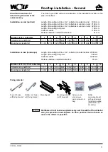
Page 10: ...e Fit compensators only to the short connectors For single sided pipework to the left see example diagram the short connectors are on the right For single sided pipework to the right rotate the collec...

Page 11: ...r mounted on end 1030 mm Length of mounting rail Alu for 2 collectors mounted on end 2160 mm Length of mounting rail Alu for 3 collectors mounted on end 3290 mm Length of mounting rail joiner 100 mm C...

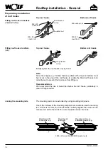
Page 12: ...washer nuts Preparatory installation of roof hooks Fitting roof hooks to battens installed before Top roof hooks Bottom roof hooks M8 x 20 coach bolt M8 x 20 coach bolt M8 x 20 coach bolt M8 washer nu...

Page 13: ...fficient numbers into the mounting rails 5 Fit the mounting rails with washer nuts onto the roof hooks 6 Cover the roof hook area with tiles C o l l e c t o r a c r o s s 1 0 6 C o l l e c t o r o n e...

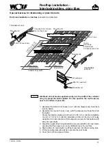
Page 14: ...rail Collector array width M8 x 20 coach bolt Where the tile valley is not above a rafter a separately available rafter compensating plate 3 is fixed above the rafter 2 and the roof hook 1 nestled in...

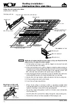
Page 15: ...mounting rails with coach bolts 4 Cover the slate hooks with commercially available lead flashing 5 Cover the roof Collector array width C ollector across 1 06 C ollector on end 2 06 Option Snow load...

Page 16: ...ed screws should be cut off flush with the nut above the mounting plate This ensures that the collector housing does not come to rest on the screws The roof skin is sealed by lightly and carefully tig...

Page 17: ...ough the top mounting rail and initially tighten by hand into the collector 3 Fit additional collectors likewise 4 Secure the fittings for the flow and return Check gaskets 5 Tighten all screws and nu...

Page 18: ...ION Screws nuts grub screws wood screws in the bag Intermediate panels Connecting rail Standard dimensions for determining the position of the collector array Position the collector array so that the...

Page 19: ...6 m Mounting rail for 1 add collector 1 13 m 2 x M8 x 16 coach bolts 4 x M8 x 16 coach bolts Wooden spacers in the thickness of the battens Triangular sealing strip Top panel Collector Wooden spacers...

Page 20: ...he wooden spacers batten thickness less 9 mm to the rafters 3 Affix the flashing tape in accordance with the diagram For this peel back the protective foil only in the area actually to be used for the...

Page 21: ...hand 4 Drill a 5 mm hole through the mounting rail and the wooden spacers into the rafter and secure to the rafter with 8 x 80 hexagon head cap wood screw 5 Secure the flow and return fittings Check...

Page 22: ...tor position Then bend the tabs at the top of the intermediate panels to prevent them from sliding through 2 Tighten all screws and nuts to secure the collector 3 Fully peel back the protective foil f...

Page 23: ...h rafter a wooden spacer of batten height must be fitted below the casing panel Secure the casing panel with clamps 3 Push the protective edge profiles at the casing panel joint at the top over the re...

Page 24: ...ray Width incl visible edging panels Min 2 7 m Min 1 m Align to the left or right Width with flashing pieces lift plates Width with flashing pieces lift plates Width incl visible edging panels Side pa...

Page 25: ...strips of flashing tape are used these must be joined with an overlap of at least 5 cm Do not yet affix the flashing tape to the roof tiles as the collectors have yet to be secured to the mounting ra...

Page 26: ...for now 4 Do not yet secure the upper mounting rail to the roof 5 Secure the flow and return fittings Check gaskets 6 Check for leaks in accordance with the section Leak testing Install the solar line...

Page 27: ...panels to prevent them from sliding through 2 Tighten all screws and nuts to secure the collector 3 Fully peel back the protective foil from the flashing tape and affix the flashing tape to the tiles...

Page 28: ...rim with scissors if necessary Ensure sufficient overlap 8 10 cm 2 Align lift plates parallel to glass retaining strip of collector at a distance of 65 mm 3 Fix the lift plates at the top with 2 nails...

Page 29: ...imension X results by which the collector must be raised in order to fit the upper edging panel Remove upper edging again and place a suitable spacer block under the top mounting rail 5 Pre drill thro...

Page 30: ...etainers each 2 Cover the joints in the top edging panel with the edge protector 3 Hook the side panels into the glass retaining strip of the collector using a rotating motion and slide them upwards u...

Page 31: ...to the battens Screws nuts grub screws wood screws in the bag Intermediate panels Connecting rail Flashing tape base right Right hand skirt Left hand skirt Standard delivery Assembly components Numbe...

Page 32: ...mmendation Stuff the space below the top panel at the tile contact point to prevent the tile from pushing through Installation and extension of the lower mounting rail Flashing tape base left Flashing...

Page 33: ...ail 3 Position the wooden spacers batten height onto the rafters at the top of the collectors Position the mounting rail on top of the wooden spacers and push against the top of the collector Initiall...

Page 34: ...g tape 1 Push in the intermediate panels as per diagram If this should foul during the installation correct the collector position Then bend the tabs at the top of the intermediate panels to prevent t...

Page 35: ...re e g with a hammer Affix the tape end to the support and the highest point Mark the width of 2 tiles along the entire length of the flashing tape and trim Affix the entire tape to the support starti...

Page 36: ...anel with clamps 3 Push the protective edge profiles at the casing panel joint at the top over the return see the diagram 4 Affix the side and top triangular sealing strip to the casing panels Install...

Page 37: ...Air vent trap 1 collector Pipework Collector sensor 6 mm Sensor well Flow connector Pipework for roof top flat roof installation Return connector Pipework for roof integration Pipework for roof integ...

Page 38: ...ng the system from being filled correctly Reducing the drain rate at the BDF valve can help prevent this situation Reduce the drain flow rate until the required system operating pressure is constantly...

Page 39: ...nd safety valve remain integrated during the pressure test If the pressure test is successful first bleed the system and then discharge ANRO until the pressure is reduced to the charge pressure of the...

Page 40: ...indication of the correct system operating pressure is an overpressure of 1 5 2 0 bar at the highest point of the system when cold The system operating pressure at the solar module is therefore 1 5 2...

Page 41: ...led O 11 Solar circuit pressure tested incl leak check on all threaded solder and compression fittings O 12 All joints glands on shut off valves and fill drain valves leak tested O 13 System pressure...

Page 42: ...ost installation check or initial inspection should be included as a component of the overall service package for the system and can be itemised separately in the quote if required The main system par...

Page 43: ...es If the cylinder is included in the service contract the cylinder should be serviced in accordance with the manufacturer s instructions If the service or inspection reveal the need for additional wo...

Page 44: ...re tested for this release pressure from expansion vessel _____bar _____bar In case of noisy pumps or system pressure fluctuations vent the system for this block the gravity brake O O System pressure...

Page 45: ...re tested for this release pressure from expansion vessel _____bar _____bar In case of noisy pumps or system pressure fluctuations vent the system for this block the gravity brake O O System pressure...

Page 46: ...re tested for this release pressure from expansion vessel _____bar _____bar In case of noisy pumps or system pressure fluctuations vent the system for this block the gravity brake O O System pressure...

Page 47: ...re tested for this release pressure from expansion vessel _____bar _____bar In case of noisy pumps or system pressure fluctuations vent the system for this block the gravity brake O O System pressure...

Page 48: ...charge pressure Safety valve has responded Check pipework for leaks Notify your specialist contractor Flow rate not correct Faulty pump Shut off valve Flow rate is dependent on temperature viscosity...

Page 49: ...ower consumption solpump W 25 25 25 25 Standby power consumption solstandby W 5 5 5 5 Annual auxiliary electricity consumption Qaux kWh 93 8 93 8 93 8 93 8 Product fiche according to Regulation EU no...

Page 50: ...p W 25 Standby power consumption solstandby W 5 Annual auxiliary electricity consumption Qaux kWh 93 8 Product fiche according to Regulation EU no 812 2013 Supplier s name or trade mark Wolf GmbH Supp...

Page 51: ...51 3062165_201508 Notes...

Page 52: ...s and EN 12975 1 specifications EN 12975 2 We Wolf GmbH Industriestra e 1 D 84048 Mainburg Germany hereby declare that the above solar collectors comply with the appropriate regulations laid down in t...

Reviews: