background image

13

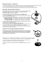
Marking Position on Table top

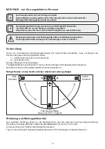
Locate the desired position of the Visualizer and its pick-up area by taking the big template and mark the 
center line and the top border of the maximum pick-up area. Then drill the table drill hole
Note: the template is showing the left half of the unit and the pick-up area, the right side is exactly.

.

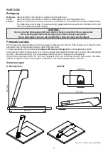
Mount  swivel  plate  by  using  the  opposite  mounting  plate 

and the screws M4x40mm Torx20 at the drill hole.

Cable guide holes should line up together.

Screw-in the screws to mount the swivel plate - 

do not tighten yet.

Turn the 

(sectional top plate of the swivel) to access the other 

thread, screw-in the second screw.

Position the swivel by taking the small template according the desired way of 
mounting: fixed, turnable (left / right).
Place the cut-out of the template onto the swivel top plate.
Move the template inclusive 

complete swivel unit 

until the bottom end and 

the center line of the template matches the markings on the table top.
Tighten the accessible screw. Turn the swivel top plate to access and tighten 
the other screw (remove teomplate).

(raised  screw 

threads facing up) 

swivel 

top

 plate 

Turn  swivel 

top

  plate  depending  on  desired  closing  direction:

Fold down to the left:

turn top plate counter-clock-wise to end position.

Fold down to the right:

turn  top  plate  clock-wise  to  end  position.

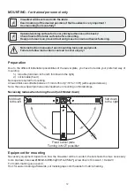
Fixed swivel plate:

turn top plate counter-clock-wise to end position.

Mounting Through Table drill Hole

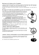
Turn  base  plate  to  working  position 

(cable  guide  holes  should  line  up 

together) Insert M3x8 screw to lock the turning mechanism.

Visualizer is locked and turning/rotating is 

not possible

 when the screw is 

placed.

Optional: Lock Top Plate of Swivel to fix the turning mechanism

Ø 4.2 mm

[~1

1/64"]

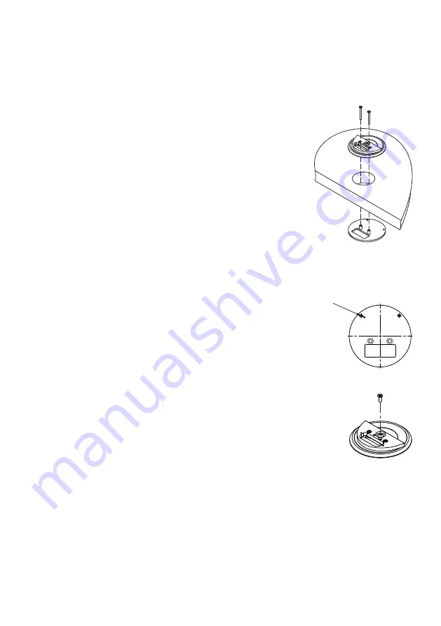
When desired, the opposite mounting plate can be secured by screwing it 
onto the table plate from underneath (use both empty holes of the plate with 
diameter Ø 4.2mm [11/64"]). Use screws with correct thread and suitable for 
the table (screws are not included).

Optional: Secure Opposite Mounting Plate

rear edge of table

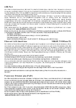
Summary of Contents for VZ-3s

Page 1: ...k out our Internet Homepage for additional information www wolfvision com support VZ 3s INSTRUCTIONS BEDIENUNGSANLEITUNG INSTRUCTIONS BEDIENUNGSANLEITUNG ENGLISH DEUTSCH VZ 3s R VIS UAL IZE R VZ 3s ZO...

Page 2: ...or damage to the CCD camera Do not pull the plug from the power socket with wet hands If the Visualizer is not used for a long time disconnect it from mains The external power supply has to be approve...

Page 3: ...al equipment Inspections tests and evaluation are according to UL60950 CSA22 22 60950 Inspections tests and evaluation are according to the CB Scheme Inspections tests and evaluation are according to...

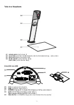
Page 4: ...cover see below Zoom wheel see next page 3 Connectors 2 5 DVI I output see page 8 6 USB port see page 7 External Input for Computer RGB signals 15pin 10 100 TBase 7 see page 9 8 LAN port see page 7 P...

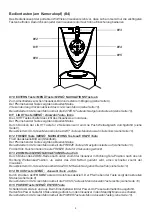
Page 5: ...p function when keeping pressed for 2 seconds 13 ZOOM WHEEL menu navigation wheel up and down Turn the wheel down to zoom in TELE and up to zoom out WIDE The more you turn the ZOOM WHEEL the faster th...

Page 6: ...ect your display device projector monitor video conferencing unit etc to the appropriate output of the Visualizer 5 RGB with adapter and fasten the cable tie IMPORTANT For choosing the right output se...

Page 7: ...esults are still not satisfactory the monitor or projector should be checked This means that the white balance is continuously adjusted automatically White Balance Adjustment 6 IMPORTANT Please note t...

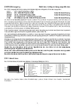
Page 8: ...USB 2 0 port can also output live motion The vSolution Link Software by WolfVision can storeAVI files and includes a video capture driver You can view and save the live image from the Visualizer on yo...

Page 9: ...higher resolutionsthan their native resolution but only in compressedmode and with inferiorpicture quality Do NOT set the output of the Visualizer to a higher standard than the native resolution of yo...

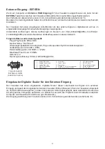
Page 10: ...re provided Plug Play Monitor VESADDC Monitor name WolfVision Video Input Definition Analog at 0 7Vpp and separated synchronization signals Vertical range limits 48Hz 86Hz Horizontal range limits 30kH...

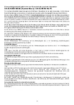
Page 11: ...e g Gain Shutter Image Brightness and Back Light Compensation The Color Settings will affect the color reproduction of the camera e g White Balance settings Color Mode and Positive Negative Hint If th...

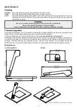
Page 12: ...n closed 507 1mm 19 96 129 8mm 5 11 Technical Specifications are Subject to Change 571 1mm 22 48 299 5mm 11 8 496 4mm 19 54 The firmware software of your Visualizer including the o can easily be upgra...

Page 13: ...ferred way of mounting 1 turnable fold down to the left fold down to the right 2 not turnable fixed Note space required for mounting Allowed thickness of table between 11mm to 35mm 7 16 to 1 3 8 with...

Page 14: ...the template matches the markings on the table top Tighten the accessible screw Turn the swivel top plate to access and tighten the other screw remove teomplate raised screw threads facing up swivel...

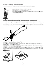
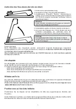
Page 15: ...tional Place Working Surface Foil Connect the Visualizer to a display device and power supply Lift the arm to working position to switch it on Clean the table to ensure adhesive fastening Zoom to full...

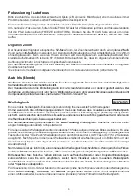
Page 16: ...rating Temperature Relative Humidity Warranty Made in 1 CCD 1 3 Progressive Scan Camera 30 frames 1280 x 960 1 228 800 1 315 648 36 864 000 very good colors SXGA 1280x960 WXGA 1280x800 HD 720p 1280x72...

Page 17: ...d das Ger t l ngere Zeit nicht benutzt so ziehen Sie bitte den Netzstecker Das verwendete Netzteil ben tigt eine europ ische Zertifizierung nach EN 60950 oder von CSA ULnach UL60950 oder Ul1950 Wei ab...

Page 18: ...g to UL60950 CSA22 22 60950 Inspections tests and evaluation are according to the CB Scheme Inspections tests and evaluation are according to the PCT Scheme Aufkleber am Ger t Pr fungen Tested to comp...

Page 19: ...ten Zoom Rad siehe n chste Seite 3 Anschl sse 2 5 6 DVI I Ausgang siehe Seite 8 Anschluss siehe Seite 7 7 9 8 7 Spannungsversorgung PoE 7 9 Kabelbinder zur Kabelfixierung zum L sen dr cken Sie die Las...

Page 20: ...das aktuelle Bild ein Standbild Der Pfeil neben derTaste zeigt den aktuellen Status Bei aktiviertem On Screen Men arbeit die FREEZE Taste als Navigationstaste auf siehe Seite 10 F r die Hilfe Funktion...

Page 21: ...sich beim Aufstellen automatisch ein Netzger t am Power Eingang 8 anschlie en Ausgabeger t Projektor Monitor Videokonferenz anlage etc an den passendenAusgang des Visualizers 5 RGB mit Adapter anschl...

Page 22: ...m Visualizer einen manuellen Wei abgleich durchzuf hren und wenn dieser kein zufriedenstellendes Resultat liefert die Einstellungen des Monitors oder Projektors zu berpr fen F Wei abgleich 6 Der Visua...

Page 23: ...ebild der Visualizer mit nahezu jedem modernen Videoschnittprogramm verarbeitet und gespeichert werden Bitte downloaden Sie die aktuellste Version der vSolution Link Software by WolfVision von unserer...

Page 24: ...Monitors Wenn eine h here Bildwiederholfrequenz als Ihr Monitor oder Projektor darstellen kann gew hlt wird kann Ihr Monitor oder Projektor besch digt werden Beachten Sie hierzu die Hinweise in der Be...

Page 25: ...gsaufl sung des Visualizers kann im On Screen Men ge ndert werden siehe Seite 10 Wenn ein Computer am Externen RGB Eingang 7 des Visualizers angeschlossen ist kann mit der EXTERN Taste 9 zwischen dem...

Page 26: ...ngen ndert Einstellungen mit Auswirkung auf die Bildhelligkeit wie z B Verst rkung Belichtungszeit Bildhelligkeitund Gegenlichtkompensation ndert Einstellungen mit Auswirkung auf die Farbwiedergabe de...

Page 27: ...einigung gegebenenfalls zusammen mit Anhauchen oder mit einem speziellen Optikreiniger WARTUNG Technische nderungen vorbehalten 496 4mm Die Firmware Ger te Software Ihres Visualizers inklusive On Scre...

Page 28: ...r Beginn der Arbeiten die gew nschteArt gew hlt werden 1 drehbar links drehend rechts drehend 2 nicht drehbar fix N tigen Platzbedarf ber cksichtigen Tischplattenst rke muss zwischen 11mm bis 35mm bet...

Page 29: ...te Swivel Platte Basisplatte gegen den Uhrzeigersinn drehen Zug ngliche Schraube festziehen Basisplatte drehen und die zweite Schraube festziehen Schablone entfernen Nun mittels der kleinen Schablone...

Page 30: ...er bis beide Schraubenbohrungen zug nglich sind optional Arbeitsplattenfolie aufkleben Bildwiedergabeger t und Netzteil anschlie en Arm hochklappen um den Visualizer einzuschalten Reinigen Sie die Kle...

Page 31: ...ung Leistungsaufnahme externes Netzteil Betriebstemperatur Relative Luftfeuchtigkeit Garantie Hergestellt in 1 CCD 1 3 Progressive Scan Kamera 30 Bilder 1280 x 960 1 228 800 1 315 648 36 864 000 sehr...

Page 32: ...9465 Fax 81 0 3 6233 9466 E mail wolfvision japan wolfvision com Canada WolfVision Canada Inc Ottawa Tel 1 613 741 9898 Toll free 877 513 2002 Fax 1 613 741 3747 E Mail wolfvision canada wolfvision c...

Reviews: