LUMINOUS™ 570 SERIES LED LIGHT BAR - PAGE 2
MOUNT LIGHT BAR - DIRECT MOUNTING
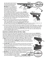
1. The light bar has two adjustable slide mounting brackets
that are designed to mount the light directly to a rack or a flat
surface such as the vehicle’s roof without using the stainless-
steel straps. IMPORTANT: The installer should always use the
stainless-steel mounting hardware provided when securing the
light bar using the direct mounting method.
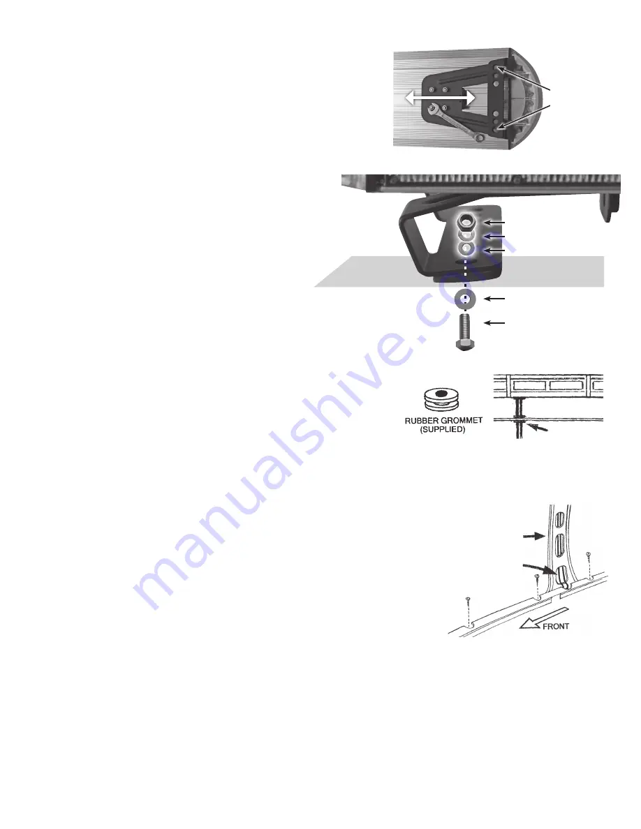
2. There are two mounting brackets on the bottom of the light
bar, one on each end. Loosen the four nuts on
one bracket and the bracket will freely slide,
repeat procedure for the other bracket. NOTE:
Do not tighten the brackets nuts until the light bar
and slide brackets have been positioned on the
mounting surface. See Fig. 1.
3. Place the light bar on the selected mounting
location. A preferred mounting position on the roof
is close to the B-pillar, which is the strongest part
of the roof. IMPORTANT: Never drill into a support
pillar. IMPORTANT: Make sure the light bar is
facing the correct direction. NOTE: There is a
label on the light’s front lens indicating ”FRONT”.
4. Position the light bar in the mounting location.
Tighten each of the slide brackets four nuts to
firmly lock the bracket in position
5. The slide bracket has pre-drilled holes designed for easy direct
mounting. Use the slide bracket as a template and mark the
locations that need to be drilled. See Fig. 1.
6. Mark the hole location for access hole to route the cables into the
interior of the vehicle. Mark the desired hole location; remove the
light bar from the roof or mounting surface. The installer must lower
the headliner before drilling any holes to carefully inspect selected
location to ensure that there are no components, wires and or any other vehicle
parts that could be damaged. WARNING: The roof has support members that spans from the driver’s side
to the passenger’s side of the vehicle, NEVER drill into a support member! It will be necessary to relocate
the cable’s access hole either in front or behind support member.
7. Drill holes: Access hole 7/16”
Mounting holes 3/8”
IMPORTANT: Protect the vehicle’s interior headliner from damage that could
be caused when drilling the access hole for the light bar’s electrical cables. It’s
recommended to allow a minimum distance of 6” to 8” between the roof and
headliner by lowering the headliner before drilling any holes.
IMPORTANT: Always de-burr the access hole that was drilled by using a round
file to ensure there are no sharp edges. NOTE: Provided with the light bar is a
rubber grommet. Insert the rubber gromet into the access hole, place the light bar
on the roof of the vehicle. Route the thin electrical wire with the plug through the
rubber grommet first, followed by the heavier gauge wire. See Fig. 3.
8. The cables will make an approximate 90° bend into the B-pillar. Depending on the vehicle, this can
sometimes be difficult, but it is the recommended procedure for proper installation. Installation can vary for
each make and model vehicle. It is up to the installation technician’s decision whether to route the cables
as recommend through the B-pillar, or use an alternative routing method. Route cables down to the bottom
of the B-pillar, and pull the full length of both cables into the interior of the vehicle. See Fig. 4.
9. Secure the light bar to mounting surface with hardware provided. See Fig 2.
10. Place a coating of silicon or weather sealant around the head of each bolt that secures the light bar to the
mounting surface. You will also need to seal the light bars wires and rubber grommet at the access hole.
This will to ensure a waterproof installation.
IF LIGHT BAR HAS BEEN DIRECT MOUNTED SKIP TO MOUNTING & WIRING SWITCH CONTROLLER ON PAGE 4
Fig. 1
RUBBER
GROMMET
Fig. 3
Fig. 4
B-PILLAR
THIN CABLE
WITH PLUG AND
HEAVY GAUGE
CABLE EXIT
DIRECT
MOUNTING
HOLES
NUT
LOCK WASHER
SMALL WASHER
LARGE WASHER
BOLT
Outside
Surface
Inside
Surface
Fig. 2

