Installation Guidelines
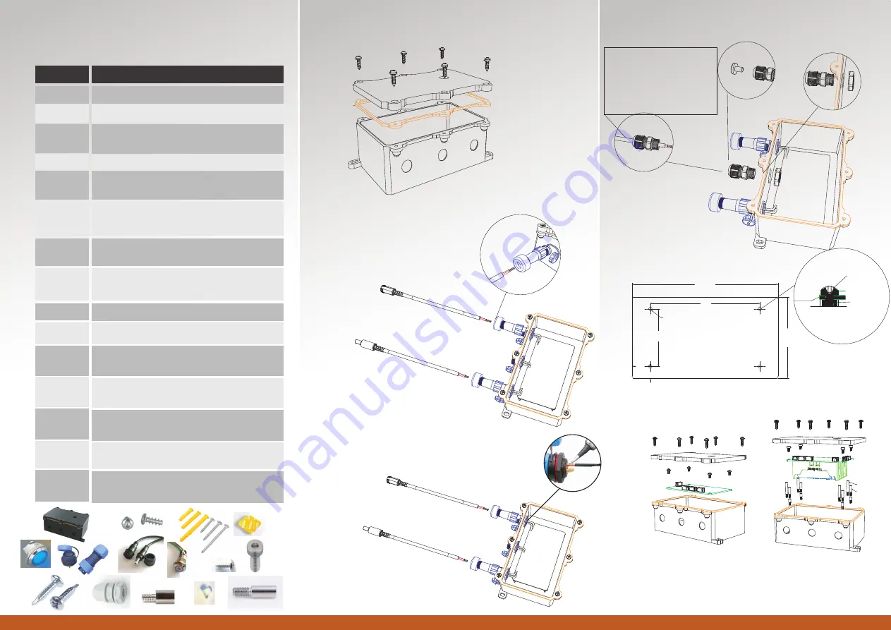
2. Attach waterproof cable(s) (such as Power Cord) to
WDC140 waterproof connector(s).
1. Attach top panel to body unit.
• Use M4 Pan Head Screw
given to attach the Top
Panel to Body Unit.
4. If one or two holes is/are unused, install PG7 Connector and
Ø5mm Waterproof Rubber Sealer Plug Cover.
3. Attach the rear core of the wire to the Printed Circuit
Board (PCB).
• Solder rear core connector
with wire to connect it.
140mm Waterproof Cabinets DIY Kit
WDC140
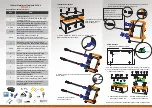
ITEM
Waterproof Cabinet
Ø12mm Waterproof Connector Plug and Socket
Ø12mm Bluetooth Button with Blue LED Light
Switch Self-recovery
Ø12mm Ball Head Curved Surface Waterproof
High-Brightness Blue LED Signal Short Type
with Wire Double Metal Indicator
QTY
1
1
1
2 Pairs
Check the box, default unit is pcs
30cm/1foot Length 0.75mm
²
2 core DC
Waterproof Power Cord 5.5x2.1mm Plug
and Socket
M3 x 30mm Expansion Tube with
M4 x 35mm, 0.7mm Pitch, Coarse Thread,
Self-Tapping Round Head Stainless Steel Screw
1 Sets
2 Sets
M4 x 35mm, 0.7mm Pitch, Coarse Thread,
Self-tapping Round Head Stainless Steel Screw
2
Ø12mm PG7 Waterproof White Nylon Connector
and Ø12mm Waterproof Rubber Sealer Plug
Cover
(25.4mm x 25.4mm x 1mm) Adhesive Tape
2 Sets
4
4
M3 x 6mm, 0.35mm Pitch, Fine Thread,
Hex Socket Cap Head Stainless Steel Screw
2
M3 x 5mm, 12mm Body Length, 0.35mm Pitch,
Fine Thread, Round Spacer Stainless Steel
Standoff
2
M3 x 5mm, 20mm Body Length, 0.35mm Pitch,
Fine Thread, Round Spacer Stainless Steel
Standoff
4
M3 x 5mm, 6mm Body Length, 0.5mm Pitch,
Coarse Thread, 8mm Hexagon Spacer
Stainless Steel Standoff
6
M4 x 12mm, 0.7mm Pitch, Coarse Thread,
Pan Head Stainless Steel Screw without washer
M3 x 5mm, 0.5mm Pitch, Coarse Thread,
Pan Head Head Stainless Steel Screw
without washer
4
PCB Guidelines
1. Dimension for placement of PCB.
2. Attach PCB to WDC140.
a. Attach PCB without batteries
to body panel of WDC140.
b. Attach PCB with batteries
to body panel of WDC140.
• PCB external dimension must be less than 127mm x 70mm (LxW) or
5” x 2.75”, installation holes distance should be 95mm x 50mm (LxW).
Pan Head Screw
Your PCB
Plastic Standoff
that attach to
Body Panel WDC140
95.00
50.00
max 127.00
m
ax 70.00
9.92
16.00
Ø3.00 clearance
thru hole x 4
For 18650 battery
For 26650 battery
Wire Information:
• Fit for 3mm to 6.5mm
diameter wire range.
• Must be single outer sheath wire.
• One of wire end must be open
ended.
Remark: For more detail, please take reference from enlarge version.


