Alignment
Blade Installation And Tracking
MHdoc012819
5-3
5
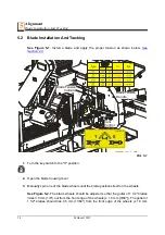
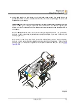
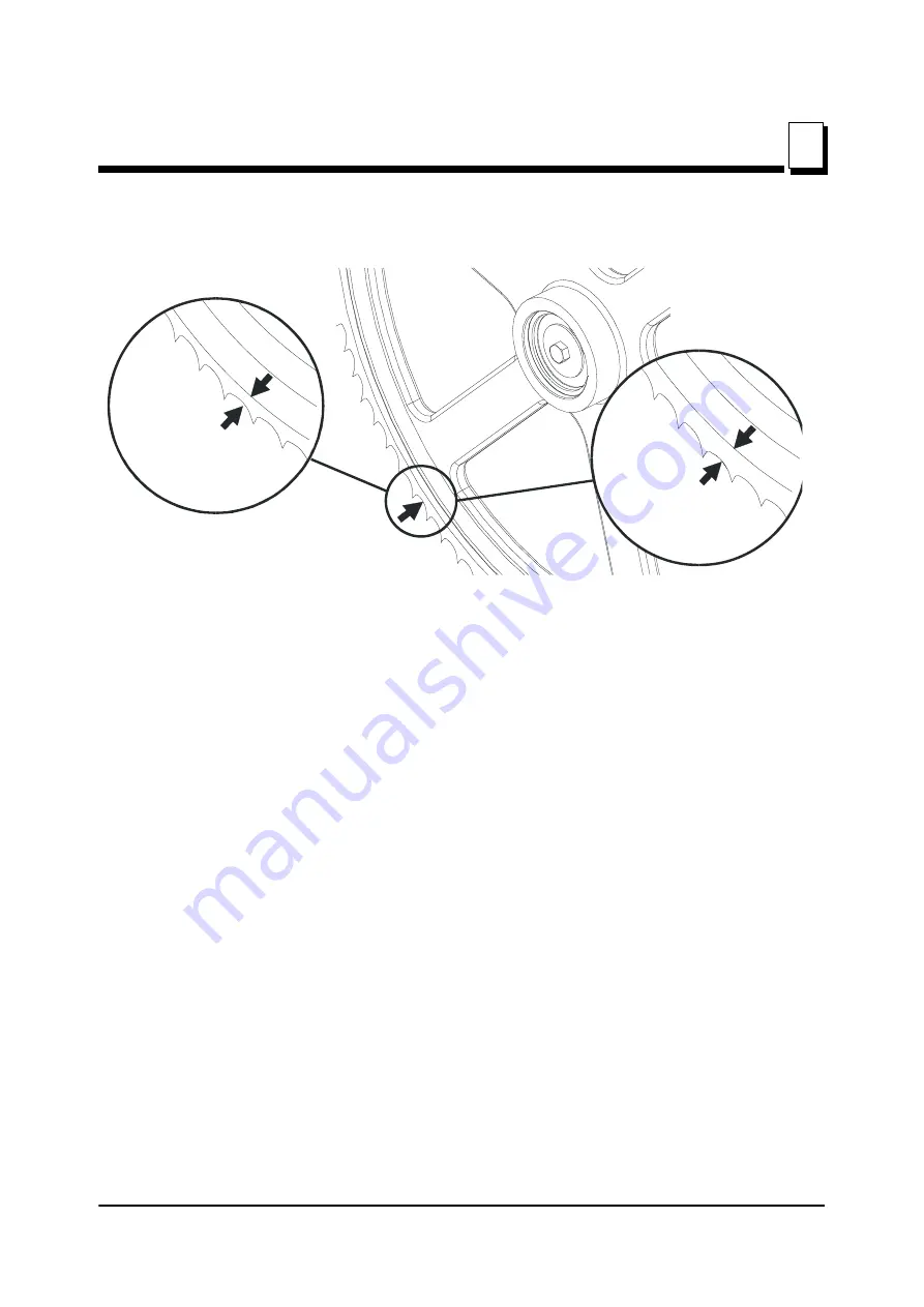
[3/64"]). Do not let the teeth ride on the belt.
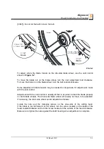
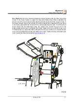
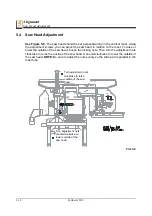
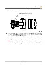
To adjust where the blade travels on the idle-side blade wheel, use the cant control
shown in
To move the blade out on the blade wheel, turn the cant adjustment bolt clockwise.
To move the blade in on the blade wheel, turn the bolt counterclockwise.
Some adjustment in blade tension may be needed to compensate for adjustments made
with the cant control.
Adjustment with the cant control is usually all that is required to track the blade properly
on both blade wheels. The drive-side blade wheel will usually not have to be adjusted.
If necessary, the drive-side wheel can be adjusted as follows:
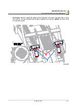
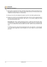
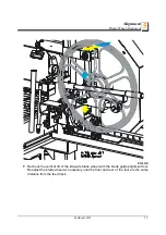
Locate the nuts and the clamping screws on the drive-side of the cutting head.
If the blade is too far forward on the wheel, turn the screw located on the inside of the
head counterclockwise and turn the screw located on the outside of the head clockwise.
Make sure to tighten the nuts against the shaft housing when adjustment is complete.
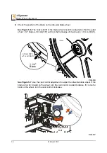
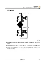
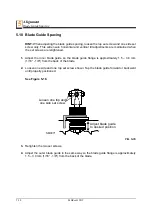
FIG. 5-2
SM0044D
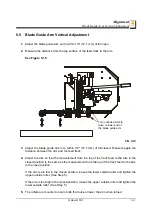
1 1/2"
Blade
1 1/4"
Blade
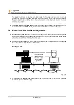
± 1 mm (3/64”)
4.5 mm (11/64”)
3.0 mm (1/8”)
± 1.0 mm (3/64”)

