Operation
Tracking the Blade
Operation
MHdoc012819
2-20
2
2.6
Tracking the Blade
1.
Open the blade housing cover.
2.
Turn the key switch to the ”H” position.
3.
Manually spin one of the blade wheels until the blade positions itself on the blade wheels.
4.
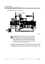
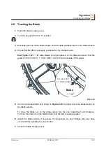
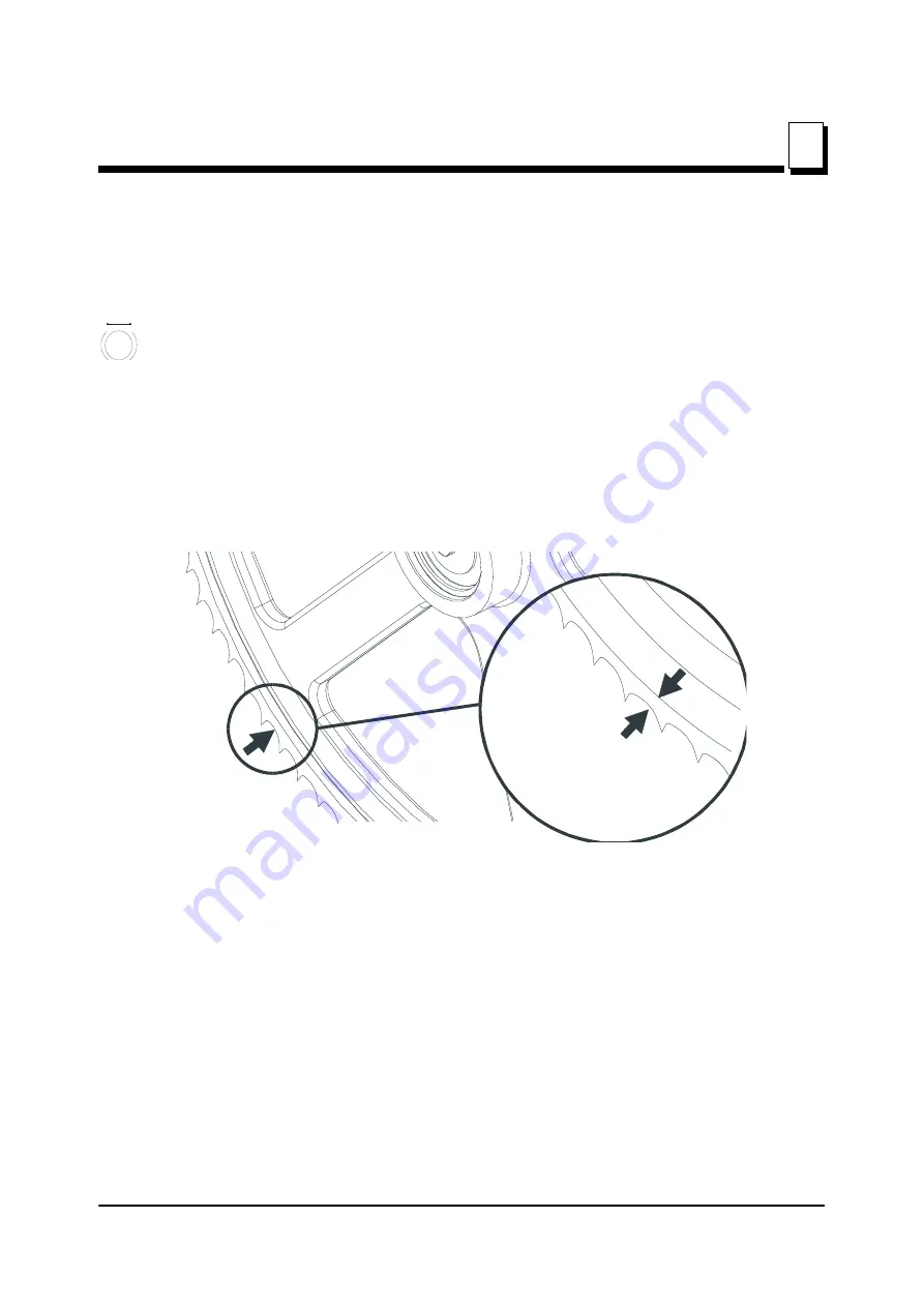
Check that the blade is properly positioned on the blade wheels.
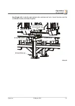
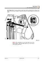
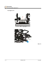
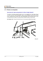
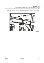
See Figure 2-12.
1 1/4” wide blades should be placed on the blade wheels so that the
gullet is 3.0 mm (1/8”) ± 1.0 mm (3/64”) out from the front edge of the wheel.
5.
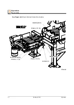
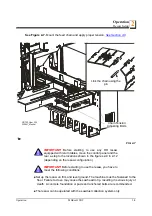
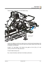
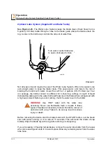
Use the cant adjustment bolt, shown in
Figure 2-10,
to adjust where the blade travels on
the blade wheels.
To move the blade out on the blade wheel, turn the cant adjustment bolt clockwise.
To move the blade in on the blade wheel, turn the bolt counterclockwise.
6.
Adjust the blade tension if necessary to compensate for any changes that may have
occurred while adjusting the cant control.
7.
Close the blade housing cover.
FIG. 2-12
H
3/16" (4.5 m
± 1/ 6" (1.5 m
1
3.0 mm (1/8”)
± 1.0 mm (3/64”)
Blade
1 1/4"
Blade

