background image

Branches & Authorized Sales CentersWood-Mizer Locations (North and South America)

-10

doc041620

GERMANY Klaus Longmuss
Wood-Mizer Sägewerke GmbH

Dorfstraße 5, 29485 Schletau
Tel.: +49-5883-9880-10
Fax: +49-5883-9880-20
e-mail: info@woodmizer.de

Klaus Longmuss

Tel.: +49-5883-9880-12
GSM: +49-17-298-55-892
e-mail: KLongmuss@woodmizer.de

Subagent:
 SWEDEN


Kjell Larsson

Mekwood AB

Slingan 14, 812 41 Gästrike-Hammarby
Tel.: +46-290-515-65

Kjell Larsson

GSM: +46-706-797-965
e-mail: kjell.larsson@mekwood.se

IRELAND
Wood-Mizer Ireland

Stephen Brennan
Cum Lahardane Ballina County Mayo
Tel:+353 96 51345

E-mail: brennanmill@ericom.net

Subagents:
DENMARK Brian Jensen

Arnborgvej 9, 7330  Brande- Fasterholt
Tel.: +45-971-88-265
Fax: +45-971-88-266

Brian Jensen

GSM: +45-23-49-5828
e-mail: Fasterholt-Savvaerk@Mail.Tele.dk

ROMANIA Adrian Echert
SC WOOD-MIZER RO SRL

TRANSILVANIEI  Nr. 5
Sibiu, Cisnadie 555300
Tel.:/Fax: : +40-369-405-433
GSM: +40-745-707-323
e-mail: aechert@woodmizer.ro

Regional Manager - Asia
Robert Moxham
Regional Direction - Asia
Wood-Mizer Asia Manufacturing Co., Ltd.
No.2, Gongyequ 40th Rd. Xitun District,
Taichung City, 40768, Taiwan, R.O.C.
TEL: +886-4-2359 3022
FAX: +886-4-2359 3205
CELL: +886-9-0568 7708
EMAIL: RMoxham@woodmizer.com
www.woodmizerasia.com
Skype: r.g.moxham

Netherlands


Chris Dragt

Lange Brink 77d, 
7317 BD Apeldoorn
Tel.: +31-55312-1833
Fax: +31-55312-2042
e-mail: Info@dragtbosbouw.nl

Subagent:
ROMANIA


M. Echert

S.C. Echert Comprod s.r.l

Str. Schitului Nr. 6, Apt.7 etajul-1
725 70 Vatra Dornei, Romania
Tel.:/Fax: +40-230-374-235
Tel. : +40-740-35-35-74

Regional Manager - Africa
Gavin Prowse
Regional Sales Director - Africa
Wood-Mizer Africa (Pty) Ltd.
Unit 1,Leader Park
20 Chariot Street
Stormill Ext.5
Maraisburg, Johannesburg
South Africa
TEL: +27 11 473 1313
FAX: +27 11 473 2005
CELL: +27 71 398 8010
EMAIL: gprowse@woodmizer.com
www.woodmizerafrica.com
Skype: gavin.prowse

USA World Headquarters

Canadian Headquarters

Serving North & South America, Oceania, East Asia

Wood-Mizer LLC
8180 West 10th Street
Indianapolis, IN 46214

Phone: 317.271.1542 or 800.553.0182
Customer Service: 800.525.8100
Fax: 317.273.1011
Email: infocenter@woodmizer.com

Serving Canada

Wood-Mizer Canada
396 County Road 36, Unit B
Lindsay, ON K9V 4R3

Phone: 705.878.5255 or 877.357.3373
Fax: 705.878.5355
Email: ContactCanada@woodmizer.com

Brazil Headquarters

Europe Headquarters

Serving Brazil

Wood-Mizer do Brasil
Rua Dom Pedro 1, No: 205 Bairro: Sao Jose
Ivoti/RS CEP:93.900-000

Tel: +55 51 9894-6461/ +55 21 8030-3338/ +55 51 3563-4784
Email: info@woodmizer.com.br

Serving Europe, Africa, West Asia

Wood-Mizer Industries Sp z o.o.
Nagorna 114
62-600 Kolo, Poland

Phone: +48.63.26.26.000
Fax: +48.63.27.22.327

Branches & Authorized Sales Centers

For a complete list of dealers, visit www.woodmizer.com

Summary of Contents for LX450 Series

Page 1: ......

Page 2: ......

Page 3: ... Safety Setup Operation Maintenance Manual LX450 E25 rev A2 02 Safety is our 1 concern Read and understand all safety information and instructions before operating setting up or maintaining this machine Form 803 ...

Page 4: ... Away Use Proper Maintenance Procedures Keep Safety Labels In Good Condition 1 7 Belt Sizes 1 14 1 8 Blade Sizes 1 14 1 9 Cutting Capacity 1 15 1 10 Motor Specifications 1 15 1 11 Noise Level 1 16 1 12 Sawdust Extractor Specifications 1 16 1 13 Overall Dimensions 1 17 1 14 Sawmill Components 1 20 SECTION 2 SETUP OPERATION 2 1 2 2 Sawmills with cable guide 2 2 2 3 Replacing the Blade 2 9 2 4 Tensio...

Page 5: ... 6 SECTION 4 TROUBLESHOOTING GUIDE 6 1 4 1 Sawing Problems 6 1 SECTION 5 SAWMILL ALIGNMENT 7 1 5 1 Pre Alignment Procedures 7 1 5 2 Frame Setup 7 2 5 3 Blade Installation And Alignment 7 2 5 4 Blade Wheel Alignment 7 5 5 5 Saw Head Slide Pad Adjustment 7 9 5 6 Adjusting The Saw Head 7 10 5 7 Adjusting Bed Rails To The Blade 7 14 5 8 Blade Guide Arm Adjustment 7 15 5 9 Aligning the Blade Guides 7 2...

Page 6: ...6 SW 07doc041620 Table of Contents Table of Contents Section Page SECTION 6 MOTOR BRAKE 8 1 6 1 Motor Brake Maintenance 8 1 Maintenance intervals Checking the rotor thickness Check the air gap ...

Page 7: ...ice Representative Please have your machine identification number and your customer number ready when you call The Service Representative can help you with questions about the operation and maintenance of your machine He also can schedule you for a service call Office Hours Please have your vehicle identification number and your customer number ready when you call Wood Mizer will accept these meth...

Page 8: ...SWITZERLAND Stefan Wespi Maschinen u Geräte Spezialarbeiten GmbH Eichistraße 4 6353 Weggis Tel 41 0 41 3900312 GSM 41 0 79 9643594 info mobilsaegen ch RUSSIA Dariusz Mikołajewski OOO WOOD MIZER INDUSTRIES 141031 Moscow Reg Mytishenski raj pos Veshki Zavodskaja str 3B Tel Fax 7 495 788 72 35 Tel Fax 7 495 641 51 60 e mail dariuszm woodmizer moscow ru BULGARIA Kalin Simeonov Ecotechproduct 38 Star L...

Page 9: ... Kerestecilik San ve Tic Ltd Sti Adana Keresteciler Sitesi 191 sk No 41 ADANA Tel 90 322 346 15 86 Fax 90 322 345 17 07 GSM 90 533 363 18 44 e mail info erkaahsap com tr FINLAND Howard Blackbourn Oy Falkberg Jordbruk Ab Falkintie 220 25610 Ylonkyla Tel 358 2732 2253 Fax 358 2732 2263 Howard Blackbourn GSM 358 440 424 339 e mail falkberg woodmizer fi LITHUANIA Andrius Zuzevicius UAB Singlis Savanor...

Page 10: ...s Dragt Lange Brink 77d 7317 BD Apeldoorn Tel 31 55312 1833 Fax 31 55312 2042 e mail Info dragtbosbouw nl Subagent ROMANIA M Echert S C Echert Comprod s r l Str Schitului Nr 6 Apt 7 etajul 1 725 70 Vatra Dornei Romania Tel Fax 40 230 374 235 Tel 40 740 35 35 74 Regional Manager Africa Gavin Prowse Regional Sales Director Africa Wood Mizer Africa Pty Ltd Unit 1 Leader Park 20 Chariot Street Stormil...

Page 11: ...ode Company Identification Number 456 Wood Mizer Indiana Weight Class A Under 1300 kg B 1301 1800 kg C 1801 2200 kg D 2201 3000kg X Stationary Product No 1 LT10 15 2 LT20 Series 4 LT40 Series 7 LT70 Series Length of the Trailer 20 20 6 m 24 24 7 m 35 35 11 m Number of axles on the trailer Year of Manufacture N 2015 P 2016 R 2017 S 2018 T 2019 State of Manufacture N Indiana P Poland Month of Manufa...

Page 12: ...o you Please write these numbers below so you have quick easy access to them Important Read the entire Operator s Manual before operating the sawmill Take notice o all safety warnings throughout this manual and those posted on the machine Keep this manual with this machine at all times regardless of ownership Customer No Model Type VIN No Revision No ...

Page 13: ...ead any additional manufacturer s manuals and observe any applicable safety instructions including dangers warnings and cautions Always be sure that all safety decals are clean and readable Replace all damaged safety decals to prevent personal injury or damage to the equipment Contact Wood Mizer Customer Service or the Wood Mizer distributor in your area to order a new decal IMPORTANT It is always...

Page 14: ...g the sawmill Failure to do so may result in serious injury or death 1 4 Sawmill Operation IMPORTANT The sawmill is intended for sawing wood only See Section Cutting Capacity for log size capacities of the machine IMPORTANT The operator of the sawmill should get adequate training in operation and adjustment of the machine DANGER Make sure all guards and covers are in place and secured before opera...

Page 15: ...Before loading a log be sure the cutting head is moved far enough forward so the log does not hit it Failure to do so may result in machine damage CAUTION Do not try to force the saw head beyond its upper and lower travel limits Failure to do so may result in damage to the up down system CAUTION Make sure the blade is stopped before returning the saw head This will not only prevent the blade from ...

Page 16: ... dry powder extinguisher 1 5 Sawmill Maintenance CAUTION The up down screw bellows should completely cover the screw If either of the bellows is damaged replace it immediately Before installing the new bellows clean the up down screw and nut thoroughly with extraction naphtha and then grease them CAUTION Reinstall the track wiper so that it lightly touches the track rail If the wiper presses too f...

Page 17: ... with the machine at all times regardless of ownership Also read any additional manufacturer s manuals and observe any applicable safety instructions including dangers warnings and cautions IMPORTANT Only adult persons who have read and understood the entire operator s manual should operate the sawmill The sawmill is not intended for use by or around children IMPORTANT It is always owner s respons...

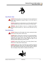
Page 18: ...o may result in serious injury WARNING Always wear eye ear respiration and foot protection as well as safety clothing when operating or servicing the sawmill Keep Sawmill and Area Around Sawmill Clean DANGER Maintain a clean and clear path for all necessary movement around the sawmill and lumber stacking areas Failure to do so will result in serious injury Dispose Of Sawing By Products Properly IM...

Page 19: ...ut off the blade motor before replacing the blade Failure to do so may result in serious injury DANGER Motor components can become very hot during operation Avoid contact with any part of a hot motor Contact with hot motor components can cause serious burns Therefore never touch or perform service functions on a hot motor Allow the motor to cool sufficiently before beginning any service function D...

Page 20: ...overs closed and securely fastened during sawmill operation WARNING Consider all electrical circuits energized and dangerous WARNING Disconnect and lock out power supply before servicing the sawmill Failure to do so may result in serious injury WARNING Never assume or take the word of another person that the power is off check it out and lock it out WARNING Do not wear rings watches or other jewel...

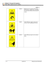
Page 21: ...ervice to order more decals IMPORTANT When replacing a component having a safety decal affixed to it make sure the new component also has the safety decal affixed See Table 1 1 See the table below for descriptions of the pictographic warning and informational decals placed on the LX450 sawmill TABLE 1 1 Decal View Decal No Description 096317 CAUTION Read thoroughly the operator s manual before ope...

Page 22: ...ion 099219 Blade tension Turning the bolt clockwise will increase the blade tension and turning the bolt counterclockwise will decrease the tension 099221 CAUTION Keep all persons away from work area when operating the machine 098176 CAUTION Keep away from the debarker blade TABLE 1 1 099219 099221 098176 ...

Page 23: ...ion doc041620 1 11 1 096316 CAUTION Do not open or close the electric box when the switch is not in the 0 position 096319 CAUTION Disconnect power supply before opening the box 096321 Blade movement direction S12004G CAUTION Always wear safety goggles when operating the sawmill TABLE 1 1 ...

Page 24: ...tion S12005G CAUTION Always wear protective ear muffs when operating the sawmill 501465 CAUTION Always wear safety boots when operating the sawmill 501467 Lubrication point P11789 Tracking the blade on the blade wheels P85070 CE certification marking 099401 Russian certification marking TABLE 1 1 099401 ...

Page 25: ...tion doc041620 1 13 1 S20097 Direction of motor revolutions P85066 Blade positioning 512158 Lubricate the chain every 50 hours of operation or once a week 512240 Clean the chain of sawdust every 50 hours of operation or once a week TABLE 1 1 S20097 P85066 3 4 mm 512158 OIL 50h 512240 50h ...

Page 26: ...l Belts B57 1 1 To insure proper blade tracking use Goodyear Dayco Super II or Browning belts only P04185 2 TABLE 1 2 Motor Size Recommended Blade For Sawing 1 1 The blade used on the LX450 sawmill is 4 54 m long Its linear speed is 22m s Softwood Hardwood Frozen or Hard To Cut Wood 5 15 HP B275IH1030 B275IH741030 B375IH929 B375IH929 2 2 TRU SHARP F blades use a 9 29 9o hook angle and 29o back ang...

Page 27: ...w for power supply specifications for the LX450E25 sawmill DANGER It is recommended that a 30mA GFI Ground Fault Interrupter be used Maximum Log Diameter Maximum Length LX450 92 cm 6 2 m TABLE 1 4 Sawmill Model Cutting Rate LX450 0 30 m min TABLE 1 5 Motor Type Manufacturer Model No Other Data Electric Motor E25 18 5 kW Siemens Germany 1LA7166 2AA60Z 3 x 400V 50 Hz 33 8A 2930 r p m Up Down Motor 0...

Page 28: ... is not possible to determine with certainty if preventives are needed or are not needed The factors affecting a current level of noise exposure during work are inter alia room characteristics and characteristics of other noise sources e g number of machines and machining operations nearby Also the permissible exposure level can vary from country to country This information however will enable the...

Page 29: ...exposed to does not exceed 2 5 m s2 The highest root mean square value of weighted acceleration to which the whole operator s body is subjected does not exceed 0 5 m s 1 13 Overall Dimensions See Figure 1 1 The overall dimensions of the LX450 sawmill are shown below See figure 1 2 Legs spacing on the LX450 sawmills and outfeed tables are shown below FIG 1 1 ...

Page 30: ...Safety General Information Overall Dimensions 1 1 18 doc041620 Safety General Information RYS 1 2 ...

Page 31: ...Safety General Information Overall Dimensions Safety General Information doc041620 1 19 1 See Figure 1 3 See the figure below for the operator s work place FIG 1 3 Operator s Work Place ...

Page 32: ...4 Sawmill Components See Figure 1 4 The major components of the LX450 sawmill are shown below FIG 1 4 Water Bottle Sawmill Mast Saw Head Up Down Drive Assembly Blade Motor Bed Frame Electric Box Control Box Log Clamp Hydraulic Control Levers Side Supports Driven Log Levelling Rollers Log Loader ...

Page 33: ...ommended The sawmill must not be operated indoors without a sawdust extraction system connected and started AC sawmills must not be used outdoors when it is raining or snowing In such a case they must be used and stored under roof or indoors The sawmill can be operated in the temperature range of 15o C to 40o C The intensity of light at the operator s work place must be at least 300lx The operator...

Page 34: ... in the power socket electric box Setting the phases in the phase inverter correctly will ensure correct rotation directions of all sawmill motors WARNING If the blade or drive belt breaks wait until all moving sawmill components stop completely Failure to do so may result in serious injury or death 2 2 Sawmills with cable guide See Figure 2 1 The figure below shows setup of the sawmill and the gu...

Page 35: ...Setup Operation Sawmills with cable guide Setup Operation 15doc041620 2 3 2 Secure the columns to the ground using 16mm anchored bolts FIG 2 1 LT450SRC ...

Page 36: ...Setup Operation Sawmills with cable guide 2 2 4 15doc041620 Setup Operation FIG 2 2 LT450MRC ...

Page 37: ...e guide Setup Operation 15doc041620 2 5 2 See Figure 2 2 The electrical wires should be installed on the guiding rail as shown below See Figure 2 3 Install the rail bracket arm as shown below FIG 2 3 FIG 2 4 7 5 1 B0 18 K GUZ M8x30 Bolt ...

Page 38: ...Setup Operation Sawmills with cable guide 2 2 6 15doc041620 Setup Operation See Figure 2 4 Install the guiding rail See Figure 2 5 FIG 2 5 9LHZ 9LHZ K 7 5 1 B0 18 ...

Page 39: ...Setup Operation Sawmills with cable guide Setup Operation 15doc041620 2 7 2 See Figure 2 6 The figures below shows how the cable hanger should be set FIG 2 6 9LHZ 9LHZ K 7 5 1 B0 18 ...

Page 40: ...Setup Operation Sawmills with cable guide 2 2 8 15doc041620 Setup Operation To remove the cable hanger from transport position unbolt hanger transport bracket FIG 2 7 ...

Page 41: ...List 804 See Section 11 4 2 3 Replacing the Blade DANGER Always disengage the blade and shut off the sawmill motor before changing the blade Disconnect the power supply using the main switch Failure to do so will result in serious injury WARNING Always wear gloves and eye protection when handling bandsaw blades Keep all other persons away from area when FIG 2 8 ...

Page 42: ... the blade wheels When installing the blade make sure the teeth are pointing the correct direction The teeth located between the blade guide assemblies should be pointing toward the sawdust chute Position 1 1 4 wide blades on the wheels so the gullet is 3 mm out from the front edge of the wheel Position 1 1 2 wide blades on the wheels so the gullet is 4 5mm out from the front edge of the wheel Clo...

Page 43: ... a shift There should be information on the sawmill that it is necessary to tension the blade before starting to use the machine again 2 5 Tracking the Blade 1 Make sure the blade housing cover is closed and all persons are clear of the blade 2 Start the motor for a moment until the blade positions itself on the wheels FIG 2 9 Type of Blade Tension Range PSI bar B375IH929 1800 2100 psi 124 145 B27...

Page 44: ...els by hand Spinning the blade wheels by hand may result in serious injury 3 Turn off the motor and check the position of the blade on the blade wheels See Figure 2 9 Position 1 1 4 wide blades on the wheels so the gullet is 3 0 mm 0 75 mm out from the front edge of the wheel FIG 2 10 1 0 mm 1 1 4 Blade ...

Page 45: ...heels use cant control bolt If the blade is too far out back the blade onto the wheel by turning the cant control bolt counterclockwise If the bade is too far in turn the cant control bolt clockwise until the gullet of the blade is the correct distance from the front edge of the wheel FIG 2 11 LX450_005 519400_Manual Cant Control Bolt ...

Page 46: ...n starting the machine for the first time check that main motor rotation direction is as indicated by the arrow located on the motor body If the rotation direction is incorrect invert the phases in the phase inverter in the power socket Setting the phases in the phase inverter correctly will ensure correct rotation directions of all sawmill motors sawmills with electric motors DANGER Make sure all...

Page 47: ...re that the emergency stop button on the left side of the control box is not turned on You can also change the phase sequence by adjusting with a screwdriver the phase inverter located in the socket on the left side of the electric box mounted on the hydraulic box DANGER Keep all persons out of the path of moving equipment and logs when operating the sawmill or loading and turning logs Failure to ...

Page 48: ...s far as it will go Logs must be rolled onto the loading arm one at a time for loading onto the bed of the sawmill 9 The front and rear toe boards should be below the bed level Once a tapered log has been loaded the front or rear end of the log may be lifted to parallel the heart of the log to the path of the blade The front toe board is raised by lifting the front toe board lever up The rear toe ...

Page 49: ...rms Leave the loading arm about halfway up while squaring the log This will stop the log from rolling off the side of the mill WARNING Always leave loading arms halfway up while a log is on the sawmill bed Failure to do so may result in serious injury or death NOTE Logs also may be loaded onto the sawmill with a tractor or other equipment specifically designed for that purpose 5 Raise the clamp up...

Page 50: ... the clamp and flip the cant To Clamp Logs 1 Raise the clamp in out lever and clamp the log against the side supports 2 Lower the turner lever until the turner arm falls below the bed 3 When the turner arm is lowered all the way the side supports will begin to lower Back the clamp off slightly and let the side supports come down until they are positioned below the level of your first few cuts To L...

Page 51: ...itch See Section 3 5 CAUTION Always make sure the up down switch moves to the neutral or off position when released to ensure that the saw head stops moving Failure to do so may result in machine damage CAUTION DO NOT try to force the saw head above the 35 88 cm mark or below the 1 2 54 cm mark Damage to the up down system may result 2 10 Blade Guide Arm Operation 1 Look down the length of the log...

Page 52: ...hich the saw head travels Turn the forward reverse switch upward to move the saw head forward Turn the switch down to move the saw head backward The middle position shown in the figure is the neutral position The power feed switch is designed to return to the neutral or off position when released If the switch remains engaged manually move it to the neutral or off position Repair the drum switch S...

Page 53: ... stop the blade when returning the carriage This will not only prevent the blade from being pulled off and ruined by a wood sliver but also will increase the life of the blade 3 Return the saw head to the front of the sawmill by turning the power feed switch down The power feed motor will bypass the feed rate switch and the saw head will automatically return at the fastest speed available Always d...

Page 54: ...te cut Cutting too slowly will waste blade life and lower production 8 As you get to the end of the log slow down the feed rate When the teeth exit the end of the log turn the feed rate all the way down Push te STOP button to stop the motor Remove the slab that you have just cut from the log 9 Use the power feed switch to return the saw head to the front of the sawmill Always disengage the blade b...

Page 55: ...engaging the blade before returning the saw head for maximum blade life and fuel economy DANGER If leaving the blade engaged for maximum production rates make sure the off bearer stays out of the path of the blade Failure to do so will result in serious injury or death CAUTION If you choose to leave the blade engaged raise the blade to clear the log before returning the saw head Failure to do so m...

Page 56: ...NOTE Keep the safety button pressed all the time the blade is driven If the safety button is released the motor stops and it needs to be restarted Press the START button on the control box to start the motor CAUTION If at any time you need to immediately stop the blade motor press the emergency stop button located on the electric box FIG 2 1 Debarker Switch Option Motor Start Button Up Down Switch...

Page 57: ... wood sliver but also will increase the life of the blade HINT Try to stop the blade while the heel of the blade is still in the log Then bring the saw head back without adjusting the blade up This lets you keep the blade at the current height setting so you can make the next blade height adjustment more quickly The power feed system includes an electric motor with a gear which moves the saw head ...

Page 58: ...his will stop the blade Remove the board from the log 2 16 Cutting the Log The following steps guide you through normal operation of the Wood Mizer sawmill 1 Once the log is placed where you want it and clamped firmly position the blade close to the end of the log 2 Use the blade height scale to determine where to make the first cut See Section 2 17 Set the blade to the desired height with the up ...

Page 59: ...the saw head 1 1 16 1 1 8 27 29 mm for each board 2 17 Blade Height Scale See Figure 2 16 The blade height scale is mounted on the vertical mast It includes a blade height indicator a centimeter scale or a quarter inch scale Blade Height Indicator The blade height indicator has two horizontal red lines on both sides Readings should be taken with eyes level with the indicator when the two red lines...

Page 60: ...ck with your customer before you saw to determine what actual finished thickness is required To use the quarter scale look at the blade height indicator Example You want to cut 1 25 mm random width boards from a log Position the blade for the first cut Adjust the quarter scale so a 4 4 mark is aligned with the red line on the indicator Make a trim cut Return the saw head for the second cut Now ins...

Page 61: ...these types of liquids are necessary to clean the blade remove it and clean with a rag Failure to do so may result in serious injury or death Before removing the blade engage the clutch brake lever DC sawmills Let the blade spin with water running on it for about 15 seconds This will clean the blade of sap buildup Wipe the blade dry with a rag before storing or sharpening If you are sawing in free...

Page 62: ... appropriately equipped pickup truck Use a forklift or an overhead crane to load the machine into the truck WARNING Keep all persons away from the sawmill while loading and unloading the machine Failure to do so may result in serious injury or death 1 Secure the sawmill to the truck bed to prevent the sawmill from shifting while it is being transported ...

Page 63: ...val Bumper Installation Optional Equipment Setup Operation 15doc041620 2 31 2 2 20 Board Removal Bumper Installation Optional Equipment Using the mounting hardware A install the board removal bumper to the sawmill frame FIG 2 5 ...

Page 64: ...eration Installation of Optional Outfeed Tables 2 2 32 15doc041620 Setup Operation 2 21 Installation of Optional Outfeed Tables 1 Unbolt the fasteners B and remove the hydraulic box top cover A FIG 2 6 FIG 2 7 ...

Page 65: ...etup Operation Installation of Optional Outfeed Tables Setup Operation 15doc041620 2 33 2 2 Disconnect the hydraulic hoses from the hydraulic box 3 Unbolt the hydraulic box from the frame FIG 2 8 FIG 2 9 ...

Page 66: ...Setup Operation Installation of Optional Outfeed Tables 2 2 34 15doc041620 Setup Operation 4 Bolt the hydraulic box to the base provided with the outfeed tables FIG 2 10 ...

Page 67: ...Setup Operation Installation of Optional Outfeed Tables Setup Operation 15doc041620 2 35 2 5 Connect the outfeed tables using the fasteners and move them against the machine FIG 2 11 ...

Page 68: ...ion Installation of Optional Outfeed Tables 2 2 36 15doc041620 Setup Operation 6 Level the tables by adjusting the legs To do this loosen the bolts A and use the bolts B to adjust the height of the tables FIG 2 12 ...

Page 69: ...Setup Operation Installation of Optional Outfeed Tables Setup Operation 15doc041620 2 37 2 7 After levelling the tables bolt them to the machine FIG 2 13 ...

Page 70: ...lation of Optional Outfeed Tables 2 2 38 15doc041620 Setup Operation 8 Insert the hydraulic hoses through the grommets in the table connection plate and hydraulic box Connect the hydraulic hoses to the hydraulic box FIG 2 14 ...

Page 71: ...Setup Operation Installation of Optional Outfeed Tables Setup Operation 15doc041620 2 39 2 9 Bolt the hydraulic box top cover provided with the tables and the old cover to the frame FIG 2 15 ...

Page 72: ...Setup Operation Installation of Optional Outfeed Tables 2 2 40 15doc041620 Setup Operation 10 Bolt the hydraulic box with the base to the outfeed table FIG 2 16 ...

Page 73: ... PROCEDURE MANUAL REFERENCE EVERY BLADE CHANGE Check blade guide roller performance SEE SECTION 4 2 Remove excess sawdust from blade wheel housings and sawdust chute SEE SECTION 4 2 EVERY 8 HOURS OF OPERATION Clean and lubricate track SEE SECTION 4 3 Remove sawdust from track roller housings SEE SECTION 4 3 f manuals forms 749 15doc041620 ...

Page 74: ...st See Section 4 4 Check blade wheel belts for wear See Section 4 6 Lubricate blade tensioner screw See Section 4 5 WOOD MIZER LT15WCSC LX100 LX450 MAINTENANCE LOG Check Engine And Option Manuals For Additional Maintenance Procedures PROCEDURE MANUAL REF ERENCE TOTAL HOURS OF OPERATION FILL IN THE DATE AND THE MACHINE HOURS AS YOU PERFORM EACH PROCEDURE A SHADED BOX INDICATES MAINTENANCE IS NOT NE...

Page 75: ...ast See Section 4 4 Check blade wheel belts for wear See Section 4 6 Lubricate blade tensioner screw See Section 4 5 WOOD MIZER LT15WCSC LX100 LX450 MAINTENANCE LOG Check Engine And Option Manuals For Additional Maintenance Procedures PROCEDURE MANUAL REF ERENCE TOTAL HOURS OF OPERATION FILL IN THE DATE AND THE MACHINE HOURS AS YOU PERFORM EACH PROCEDURE A SHADED BOX INDICATES MAINTENANCE IS NOT N...

Page 76: ...ast See Section 4 4 Check blade wheel belts for wear See Section 4 6 Lubricate blade tensioner screw See Section 4 5 WOOD MIZER LT15WCSC LX100 LX450 MAINTENANCE LOG Check Engine And Option Manuals For Additional Maintenance Procedures PROCEDURE MANUAL REF ERENCE TOTAL HOURS OF OPERATION FILL IN THE DATE AND THE MACHINE HOURS AS YOU PERFORM EACH PROCEDURE A SHADED BOX INDICATES MAINTENANCE IS NOT N...

Page 77: ...e by filling in the machine hours and the date you perform each procedure This symbol identifies the interval hours of operation which each maintenance procedure should be performed Be sure to refer to option and motor manuals for other maintenance procedures 3 1 Wear Life See Table 3 1 This chart lists estimated life expectancy of common replacement parts if proper maintenance and operation proce...

Page 78: ...ry 50 hours of operation remove the power feed drive wheel cover C optional equipment and remove any sawdust from the sprockets and cover 3 4 Vertical Mast Rails Clean and lubricate the vertical mast rails every 50 hours of operation Clean with solvent and remove any rust with a light grade sand paper Lubricate the mast with motor oil or automatic transmission fluid e g Dextron II or III CAUTION N...

Page 79: ...Remove the blade housing covers blade and idle side blade wheel Push the idle side shaft housing all the way in to collapse the rear tensioner piston and fully extend the front piston The front piston should reach the threaded area of the piston guide NOTE If the hydraulic fluid level is extremely low collapsing the rear piston may not fully extend the front piston If it does not finish the fill p...

Page 80: ...e head all the way to the top of the vertical mast Secure the saw head with the chain or spacers Find the chain adjusting bolt at the bottom of the mast Loosen the nut and move the sprocket down until the center of the chain is deflected 2 5cm 0 787 with a 2 3 KG 5 5 lbf 24 5 N deflection force DANGER Always secure the cutting head with a chain or board before adjusting the up down chain The cutti...

Page 81: ... Check the mill alignment every setup See Section 6 Alignment 3 Make sure all safety decals are clean and readable Remove any sawdust and dirt Replace any damaged or unreadable decals immediately Order decals from your Customer Service Representative 4 Check the power feed and up down chain every 100 hours of operation Replace if damaged FIG 3 2 50 100 ...

Page 82: ...usage of the machine E STOP button and its circuit Circuits with the E STOP button pressed Blade cover safety switches and their circuit Up down limit switches 1 Inspection of the E STOP Button and its Circuit A Start the main motor Press the E STOP button located on the left side of the control box The main motor should be stopped Pressing the START button should not start the motor until the E S...

Page 83: ...TOP button pressed try to move the saw head up and down using the switch B and Setworks button C and forward backward using the power feed switch D Both systems should not start With the E STOP button pressed try to start the debarker blade motor E and move the debarker arm F The debarker should remain turned off 3 Inspection of the blade cover safety switches and their circuit Turn on the main mo...

Page 84: ...ld remain stopped until it is restarted with the START button 4 Inspection of the Up Down Limit Switches Move the saw head up until the upper limit switch is activated The saw head should be stopped Now the saw head should move downwards only Move the saw head down until the lower limit switch is activated The saw head should be stopped Now the saw head should move upwards only ...

Page 85: ...g sharpened completely See Sharpener Manual Blades Break Prematurely Rubber belts on blade wheels worn to a point that blade contacts metal pulley look for shiny spots on edge of wheels Change blade wheel belts B 57 Poor sharpening techniques See Sharpener Manual Tension too tight Tension blade to recommended specifications Blade Does Not Track Right On Wheels Cant adjustment is incorrect Readjust...

Page 86: ...urface of the pad should touch the mast Adjust the pads Lumber Is Not Square Side supports not square to bed Adjust side support Blade not parallel to bed rails Adjust bed rails parallel to blade Sawdust or bark between cant and bed rails Remove particles Tooth set problem Resharpen and reset the blade Sawdust Builds Up On Track Excessive lubrication Do not lubricate track with grease Track is sti...

Page 87: ...he lower track rollers if necessary See Section 5 18 3 Check and adjust the vertical alignment of the blade guide arm See Section 5 8 4 Check and adjust the horizontal alignment of the blade guide arm See Section 5 9 5 Check and adjust the vertical angle of the blade guides See Section 5 11 6 Check and adjust the horizontal angle of the blade guides See Section 5 13 7 Check and adjust the spacing ...

Page 88: ...Raise the middle blade housing cover and make sure all persons are clear of the open side of the saw head 2 Turn the key switch to the position 2 3 Manually spin the idle pulley 4 Remove the key and check the position of the blade on the blade wheels Check the vertical alignment of the idle side blade wheel The gullet of the blade should ride the same distance from the front edge of the wheel at t...

Page 89: ... all that is required to track the blade properly on both blade wheels The drive side blade wheel will usually not have to be adjusted If necessary the drive side wheel can be adjusted as follows See Figure 5 3 For horizontal adjustment use the horizontal adjustment nuts If the blade is running too far back on the drive side blade wheel locate the long U bolt on the right which mounts the bearing ...

Page 90: ...ive side wheel is factory set and should not need to be adjusted If adjustment is needed use the vertical adjustment bolt To tilt the wheel upward loosen the jam nut and turn the vertical adjustment bolt clockwise To tilt the wheel downward loosen the jam nut and turn the vertical adjustment bolt counterclockwise Be sure to tighten the jam nut FIG 5 3 Vertical Adjustment Bolt Horizontal Adjustment...

Page 91: ... saw carriage so the front end of the tool is positioned over the first bed rail Measure from the bottom of the tool to the top surface of the bed rail 3 Move the saw carriage so the rear of the tool is positioned over the bed rail Again measure from the bottom of the tool to the bed rail 4 If the two measurements differ by more than 1 5 mm adjust the vertical tilt of the drive side blade wheel Se...

Page 92: ... front and rear ends of the tool differ by more than 1 5 mm adjust the vertical tilt of the idle side blade wheel See Figure 5 6 Use the vertical adjustment screws to adjust the idle side blade wheel To tilt the wheel up loosen the bottom adjustment screw one quarter turn Loosen the jam nut on the top adjustment screw and tighten the screw Tighten the top and bottom jam nuts To tilt the wheel down...

Page 93: ... 7 The horizontal tilt of the blade wheel should be adjusted so that the gullet of an 1 1 4 blade is 3 0 mm out from the front edge of the wheel 1 0 mm See Figure 5 8 Use the cant control adjustment to adjust the idle side blade wheel If the blade is too far forward on the wheel turn the cant control counterclockwise If it is too far back on the wheel turn the cant control clockwise FIG 5 6 FIG 5 ...

Page 94: ...heel The blade should be positioned on the wheel as described for the idle side blade wheel Adjust the drive side blade wheel if necessary See Figure 5 9 Loosen the jam nut on the adjustment screws Use the horizontal adjustment screws to adjust the drive side blade wheel Tighten the jam nut FIG 5 8 FIG 5 9 Cant Control Adjustment Screws ...

Page 95: ...m it underneath Check two pads with adjustment bolts A They should be touching the mast There should be a small gap about 0 2mm wide between the inner pad and the mast WARNING Always secure the cutting head with a chain or a brace before adjusting the mast pads The cutting head may fall causing severe injury or death 2 Loosen the locking bolts B and turn the adjusting bolt A as necessary to provid...

Page 96: ...ot use the mast roller with adjustment A Loosen the locking bolt B and lower or raise the roller Tighten the locking bolt See Figure 5 12 2 Using the feed controls move the saw carriage so that the blade is positioned over the front cross beam 3 Adjust blade guides so that they do not touch the blade 4 Raise the cutting head until the bottom of the blade is 400 mm above the cross beam 5 Using a ta...

Page 97: ...nment Adjusting The Saw Head Sawmill Alignment HDSdoc041620 5 11 5 See Figure 5 13 6 If the distance is not equal adjust left and right up down chain using the up down chain adjustment bolts FIG 5 13 400mm to blade ...

Page 98: ...top bolt Lower the saw head until it is 25 mm over the bed rail Adjust the stop bolt so it stops the saw head when it is 25mm over the bed rail CAUTION It is important that the lower stop bolts are properly adjusted to secure the carriage on the track rail Failure to properly adjust the stop bolts can cause saw head damage FIG 5 14 Up Down Chain Adjustment Bolts ...

Page 99: ...Sawmill Alignment Adjusting The Saw Head Sawmill Alignment HDSdoc041620 5 13 5 See Figure 5 15 FIG 5 15 Lower Stop Bolts 25mm ...

Page 100: ...m of the blade and the bed rail at each end of the bed rail Both distances should be equal See Figure 5 16 4 Loosen the bed rail clamping bolts and turn the adjustment bolts to move the bed rails to the blade if necessary 5 Re tighten the clamping bolts and adjustment bolts 6 Without changing the saw head height check all bed rails Adjust them so that all measure the same distance from the blade a...

Page 101: ...cuts A loose blade guide arm can also cause blade vibration 1 Adjust the blade guide arm in to 15 mm 1 2 from fully closed 2 Manually try to move the arm up and down If you can move the arm by hand you will need to tighten the arm rollers See Figure 5 17 Loosen the locking nuts Next loosen the jam nuts and turn the adjustment bolts in to tighten the blade guide arm rollers Re tighten the jam and l...

Page 102: ... open and remeasure the distance from the roller flange to the back of the blade The two measurements should be the same If not adjust the outer rollers in or out to tilt the arm horizontally See Figure 5 19 Loosen the mounting bolt Loosen the horizontal adjustment bolt jam nuts To tilt the arm in toward the blade loosen the right bolt and tighten the left bolt To tilt the arm out away from the bl...

Page 103: ...closed raise or lower the saw head until the bottom of the blade guide block is 15 375 mm from the top of the bed rail See Figure 5 20 Adjust the blade guide arm to 1 2 15 mm from fully open Measure the distance from the bottom of the blade guide mounting block to the bed rail This measurement should be 15 376 mm If the measurements are not the same adjust the blade guide arm vertically FIG 5 19 L...

Page 104: ...nment See Figure 5 21 Loosen the vertical adjustment bolt jam nuts To tilt the blade guide arm down loosen the rear bolt and tighten the front bolt To tilt the blade guide arm up loosen the front bolt and FIG 5 20 Measure from blade guide arm to bed rail with arm open and closed ...

Page 105: ...e Guide Arm Adjustment Sawmill Alignment HDSdoc041620 5 19 5 tighten the rear bolt Retighten the jam nuts and recheck the blade guide arm vertical tilt FIG 5 21 Front Vertical Adjustment Bolt Rear Horizontal Adjustment Bolt ...

Page 106: ...e saw head It is referred to as the outer assembly and is adjustable for various widths of materials to be processed Blade guide alignment includes four steps Blade Deflection Blade Guide Vertical Tilt Blade Guide Flange Spacing Blade Guide Horizontal Tilt Perform the blade guide alignment after you have aligned the blade on the wheels and adjusted the blade and blade guide arm parallel to the bed...

Page 107: ...uides Make sure the two set screws shown are threaded into the blade guide shaft until they touch each other See Figure 5 22 3 Loosen the bottom jam nut and tighten the top jam nut until the blade guide deflects the blade down 4 0 mm 4 Repeat for the other blade guide NOTE Be sure that the blade guide deflector rod clears the blade on both guide assemblies The rod on the outer guide assembly shoul...

Page 108: ...ying flat on the blade See Figure 5 23 3 Measure the distance from the bed rail to the bottom of the tool NOTE If the sawmill is equipped with stainless steel bed rail covers be sure to measure from the blade guide alignment tool to the top surface of the cover rather than the bed rail tube 4 Move the carriage so that the front end of the tool is positioned above the bed rail 5 Measure the distanc...

Page 109: ...om the bed rail to the tool equals the other two measurements taken 10 Move the tool close to the other blade guide and repeat the previous steps NOTE If major adjustments to blade guide tilt were made measure the distance between the blade and the bed rails again to ensure the correct 4 0 mm blade guide deflection Adjust if necessary FIG 5 24 Sm0070c Loosen jam nuts and turn screws to tilt roller...

Page 110: ...de so the blade guide flange is approximately 3 0 mm from the back of the blade 2 Loosen one side and one top set screw shown Tap the blade guide forward or backward until properly positioned See Figure 5 25 3 Retighten the two set screws 4 Adjust the outer blade guide in the same way so the blade guide flange is approximately 3 0 mm from the back of the blade FIG 5 25 Loosen one top and one side ...

Page 111: ...ween the back edge of the blade and the ruler at the end closest to the inner blade guide B 4 Measure between the back edge of the blade and the other end of the ruler A 5 The roller should be tilted slightly to the left A B 1 4 6 mm 6 Use the side set screws to adjust the horizontal tilt of the roller 7 Repeat steps 3 7 for the inner blade guide roller NOTE Once the blade guides have been adjuste...

Page 112: ... 27 Loosen both nuts and retaining bolts Use the adjustment bolt to raise or lower the disc until its distance from the blade is 0 3 0 5 mm Then retighten the retaining bolts so that the disc is parallel to the blade Retighten the retaining bolt nuts See Figure 5 28 The gap between the disc and the blade should measure 0 3 0 5 mm FIG 5 27 FIG 5 28 Sm0205pl_b Adjustment bolt Loosen both nuts and re...

Page 113: ...ts at both ends of the side support to make sure that it is parallel to the bed rail 3 Use the two lower bolts to adjust the side support so the distances A and B are equal 4 Repeat for remaining side supports See Figure 5 29 5 Swing the side support up to adjust the side support in vertical plane 6 Place a flat board across the bed rails 7 Pull back at the top of the support to eliminate slack as...

Page 114: ...rizontal and Vertical Adjustment of Manual Side Supports 5 5 28 HDSdoc041620 Sawmill Alignment 10 Repeat for the remaining side supports See Figure 5 30 FIG 5 30 Manual Side Support Square Board Locking Bolt Adjustment Arm ...

Page 115: ... at the top of the support to eliminate slack as if a log were being clamped against it See Figure 5 31 4 Check the angle of each support with a square on the board 5 The side support should be 90 to the bed rails Using the adjustment nuts adjust the side support 6 Repeat for the remaining side supports 7 Raise the side support and check if they are on the same level FIG 5 31 Side Support Square B...

Page 116: ... Adjustment of Side Supports 5 5 30 HDSdoc041620 Sawmill Alignment See Figure 5 32 Use the adjustment nut to set the side support so the distances A and B are equal FIG 5 32 Measure Distances A and B Adjustment Nut A B ...

Page 117: ...620 5 31 5 5 17 Clamp Stop Stop Bolt Adjustment 1 Once the side supports are aligned tie a string across the side supports See Figure 5 33 2 Loosen the clamp stop bolts and adjust the clamp stop until it touches the string FIG 5 33 Adjust clamp stop to string Measure Dis tances ...

Page 118: ...he blade to the top of the bed rail or stainless steel sleeve if applicable See Figure 5 34 2 View the blade height scale with eyes level with the indicator 3 Loosen the indicator bracket mounting bolts and adjust the bracket until the indicator is aligned with the correct mark on the scale Retighten the bracket mounting nut For example if the measurement from blade to bed rail was 14 3 4 375 mm m...

Page 119: ...mper Adjustment Sawmill Alignment HDSdoc041620 5 33 5 5 19 Board Removal Bumper Adjustment See Figure 5 35 Lightly compress the lower springs using the nuts shown below A Make sure the bumper roller is below the bed rail level FIG 5 35 ...

Page 120: ...til the run in operation of the friction surfaces has been completed After replacing the rotor run in armature plates and flanges have an increased initial rate of wear Checking the rotor thickness DANGER The motor must not be running when checking the rotor thickness Remove the motor cover and seal ring if mounted Measure the rotor thickness with a caliper gauge On brakes with friction plates obs...

Page 121: ... adjust the air gap to sLürated Brake type sLürated 0 1mm 0 05mm sLümax Service brake Max adjustment permissible wear Rotor thickness Excess of the adjuster nut hEmax mm min 1 mm max mm INTORQ BFK458 25 0 4 mm 1 64 1 0 mm 3 64 4 0 mm 5 32 12 mm 15 32 16 mm 5 8 17 mm 43 64 TABLE 6 2 ...

Page 122: ...Motor Brake Motor Brake Maintenance 6 8 3 EGdoc041620 Specifications ...

Page 123: ...the machine SAWMILL Model LX450 Type No of manufacturer Is in conformity with the following EC directives EC Machinery Directive 2006 42 EC EC Electromagnetic Compatibility Directive 2014 30 EU And is in conformity with the following Harmonized Standards PN EN ISO 12100 2012 PN EN 1807 2 2013 08 PN EN ISO 14120 2016 03 PN EN 349 A1 2010 PN EN ISO 13849 1 2016 02 PN EN 60204 1 2010 PN EN ISO 13857 ...

Reviews: