SETUP & OPERATION
MP360 Moulder Assembly
3
3-1
EGdoc071420
SECTION 3 SETUP & OPERATION
3.1
MP360 Moulder Assembly
Some of the machine components need to be assembled by the user before first usage.
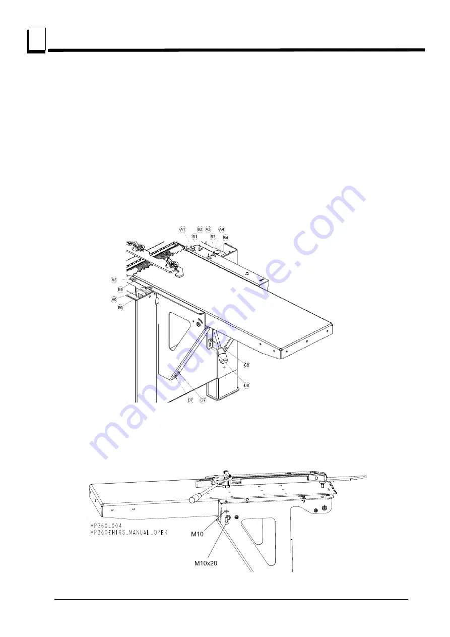
1. Infeed table.
Completely screw in all the adjusting screws (B). Install the mounting screws (A) and
tighten by hand. Install adjusting screws (C7, C8) and using them adjust the table, so it is level. Using
adjusting screws (B) set the height of the infeed table so it is at the same height as the moulder cast
iron table (double check this with a long, straight tube or flat board) and the tables touches each
other. Tighten the mounting screws (A). Tighten bottom mounting screws (D7, D8) and re-check the
table level and height.
See figure 3-1.
2. Guide fence.
Mount the guide fence according to the figure below.
See figure 3-2.
FIG. 3-1
FIG. 3-2


