SETUP & OPERATION
Side cutter
EGdoc071420
3-18
3
GRINDING
To sharpen the knife, you can grind the flat side of the knife. Always grind the knives in pairs, so that
they have the same weight, otherwise vibrations could occur in the cutter.
If the profile of the knife is damaged, this should be re-ground by a professional knife sharpener. This
is a service that is normally available locally, otherwise contact Wood-Mizer.
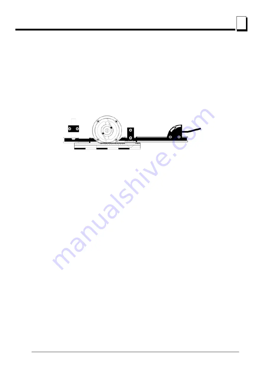
ADJUSTING THE FENCE BY CUTTER 2
See figure 3-18.
In general
The front side fence has a double set of holes for assembly. It can therefore be assembled in two
basic positions. When the TB90 system is used, the fence will be fitted in the pair of holes on the
right, as seen from the infeed side (see assembly of side fence). When cutters with larger
diameters are used, the fence can be moved to the left pair of holes, so that the stroke length is
sufficient.
The fixed cutter has two fences, the front (62) and the back fence (54). The front fence controls how
much the cutter cuts, and the back fence works as a support for the workpiece when it has passed
cutter 2 and is ready to be worked by cutter 3.
Both fences must be in line with one another, but offset in parallel so that the front fence is slightly
more to the right (see fig.). In this way, the back fence will support the workpiece once it has been cut
by cutter 2 (the workpiece is slightly smaller then).
The fence is fixed by socket head screws in the fence holders (55) according to fig. The screws that
lock the fence in the horizontal direction are 13 mm (5/10") hexagonal screws and sit in the fence's U
profile. In addition, there are micro adjustments on the fence. When the hexagonal screws are
loosened slightly, the knob for micro-adjustments can be turned. If the angle of the fence needs to be
adjusted, both the hexagonal and socket head screws must be loosened.
INSTALLATION OF SIDE FENCES
Method 1:
Insert the first fence inwards, for minimal cut- ting. Add a straight aluminum fence rail tight
against the fence. Adjust the fence using the lever until the loose fence rail touches the cutter’s
plane diameter (the outer rotating line) as it lies against the first fence.
FIG. 3-18


