R
WOODBRIDGE
R
WOODBRIDGE
R
WOODBRIDGE
R
WOODBRIDGE
R
WOODBRIDGE
R
WOODBRIDGE
R
WOODBRIDGE
R
WOODBRIDGE
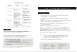
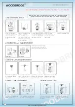
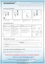
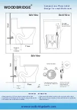
ADJUSTMENT & MAINTENACE (FILL VALVE)
Instructions:
When valve installed, the critical level mark
on fill valve (identified by C.L. mark on
valve body) shoud be at least 1" above top
of the over flow pipe.
Required:
• Water temperature: 36-112ºF
Important:
Under no circumstances seller shall not be liable for any and
all incidental damages sustained in connection with this
product
Neither manufacture, nor distributor, nor retailer is
responsible for water damage or flood caused due to use of
this product.
Under no circumstances seller shall not be liable for any and
all fees, cost of installation/reinstallation/removal,
subsequent damage or transportation in case of the product
defect
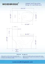
95mm
58mm
M
ax 289mm, M
in 189mm
(M
ax 344mm, M
in 244 mm
)
M
ax 230
mm, M
in 90mm
(M
ax 285mm, M
in 145
mm
)
Max 19.5mm - Min 8.5mm
45mm
WL
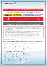
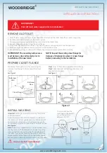
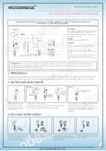
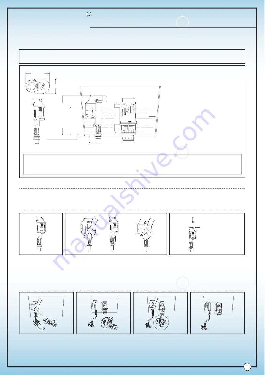
Remove the worn-out fittings and clean your tank prior to the installation of the new ones. There might be a lot of impurities in your
tank that may cause damage to the new parts if you do not clean them out. The tank must be absolutely clean prior to installation.
Check the fill valve and
make sure that it does
not have any damaged or
missing parts
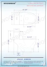
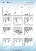
1. Press buckle and unscrew.
2. Pull the valve upwards or press down to desired height.
3. Unscrew the valve body and fasten the buckle
Rotating screw, rise or lower the water level
to adjust water level to suitable position
(water volume will gradually increase when
the adjuster is moved upward from the
bottom.)
1. PREPARATION
2. WATER LEVEL ADJUSTMENT
Press and
unscrew
Solution 1
Pull upwards
press down to
desired height
Unscrew
clockwise
and fasten
valves
Rotate screw to adjust
desired water level
Solution 2
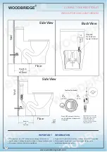
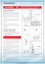
Install the valve into tank. Do
not use any wrench tools.
Fasten with hand only.
Connect water supply to the fill
valve. Turn on water.
Turn off water supply valve
before height adjustment of the
toilet's fill valve.
Put the refill tube into the white
cap hole firmly.
3. FILL VALVE INSTALLATION
IMPORTANT:
Do not use or drop any chlorine or any other chemicals. Use of chemical products will result in damage to the fill
valve and flush valve components and may cause flood and property damage. Do not overtighten bolts/nuts as it may and will
cause damage to the toilet parts and componets.
Important Note: Flush GPF amount is factory set. No addi
ti
onal adjustment is required. This page is for reference only.
All adjustments are already made by manufacturer.
C.L.
8
www.woodbridgebath.com
R
WOODBRIDGE
COMPACT ONE PIECE TOILET