background image

BANDSAW


BS

450A

Instruction 
Manual

IMPORTANT


For  yoursafety

read 

instructions


carefully before 

assembling  or using this 

product. Save  this  manual 

for


future reference. 


Original Instruction

V.

2

-201

9

10

Summary of Contents for BS450A

Page 1: ...BANDSAW BS450A Instruction Manual IMPORTANT For yoursafety read instructions carefully before assembling or using this product Save this manual for future reference Original Instruction V 2 201910 ...

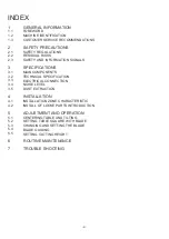
Page 2: ...DUAL RISKS SAFETY AND INFORMATION SIGNALS SPECIFICATIONS MAIN COMPONENTS TECHNICAL SPECIFICATION ELECTRICAL CONNECTION NOISE LEVEL DUST EXTRACTION INSTALLATION INSTALLATION ZONE CHARACTERISTIC INSTALL OF LOOSE PARTS INTRODUCTION ADJUSTMENT AND OPERATION CENTERING TABLE AND TILTING SETTING TABLE SQUARE WITH BLADE CHANGING AND SETTING THE BLADE BLADE GUIDING SETTING CUTTING HEIGHT ROUTINE MAINTENANC...

Page 3: ...the manufacturer s data serial number year of construction and technical specifications 1 3 CUSTOMER SERVICE RECOMMENDATIONS Apply the machine to skilled and authorized technical staff to carry out any operation dealing with parts disassembly Keep to the instructions contained in this manual for the correct use of the machine CAUTION Only the skilled and authorized staff shall use the service the ...

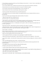
Page 4: ...efore start machine check if lock main blade and scoring blade After starting machine check if turning direction of main blade and scoring blade is right start to work after revolving speed is stable Never cutting on log directly Many unpleasant experiences have shown that anybody may wear objects which could cause serious accidents Therefore before starting working take any bracelet watch or ring...

Page 5: ...tool rotation due to incorrect electrical connection Danger due to dust inhalation in case of working without vacuum cleaner 2 3 SAFETY AND INFORMATION SIGNALS This signal may be applied on the machine in some cases they indicate possible danger conditions in others they serve as indication Always take the utmost care Risk of eye injury Wear eye protection Wear hearing protection systems Danger of...

Page 6: ...rt 12 Dust port 13 Motor 14 Rip fence 15 Blade tension knob 16 Quick tension handle 3 2 TECHNICAL SPECIFICATION SPECIFICATION BS450A Motor voltage 220 240V 50Hz Power 3HP Blade length 3886mm Blade width 6 35mm Max cut depth 330mm Throat width 445mm Blade speed 1000m min Table size 400X546mm Table tilt 10 45 Table height to floor 900mm 6 1 2 3 4 5 6 7 8 9 10 11 12 13 14 15 16 ...

Page 7: ...nd other adjacent machining The permitted exposure values may also vary from country to country Nevertheless this information allows the user of the machine to better evaluate the dangers and risks Other factors which reduce exposure to noise are correct tool choice tool and machine maintenance use of hearing protection systems e g headsets earplugs WARNING Please use the hearing protection system...

Page 8: ... INTRODUCTION A few elements will be disassembled from the machine main structure due to packaging and shipping requirements These loose parts should be installed as follows WARNING Please tighten all bolts and nuts absolutely Otherwise may cause machine wobble or serious injury to the operator or other persons 4 2 1 INSTALL TABLE Tools required for assembly Faucet spanner Put the table A onto the...

Page 9: ...ree with the blade then adjust the pointer to 0 degree 5 3 CHANGING AND SETTING THE BLADE This band saw is factory equipped with a general purpose wood cutting blade the blade set To change the blade remove the connect board from the table Then loose the quick tension handle C and blade tension handle A take down the blade After change blade firstly adjust tension handle C then adjust blade tensio...

Page 10: ...inter not set accurately 2 Adjust pointer and check blade with square 3 Miter gauge out of adjustment 3 Adjust miter gauge Blade wanders during cut 1 Fence not aligned with blade 1 Check and adjust fence 2 Warped wood 2 Select another piece of wood 3 Excessive feed rate 3 Reduce feed rate 4 Incorrect blade for cut 4 Change correct type blade 5 Blade tension not set properly 5 Set blade tension acc...

Page 11: ...OTE Please reference the Manufacturer s Part Number when calling for Replacement Parts For Parts under Warranty the Serial Number of your machine is required FRAME ASSEMBLY 95 98 99 96 97 100 101 14 11 12a 12b 13 102 103 ...

Page 12: ...862D2Z 1 M6X12GB70D1Z Hex socket cap screw M6X12 Relay 2 101 102 103 Foot switch 1 LA42J Q T 02F 1 B 117T 1B 117T 040V 001S 2 1 JL20072003 Rubber sheath 2 2 JMBS1801092000 1 D 040V 1 1 11 1 JMBS1801010009 040V Switch plate 1 12a 1 LA39 B2 10 g Switch on 1 12b 1 LA39 B2 01 r Switch off 1 13 1 LA39 B2 R02Z R Emergency switch 1 818D1Z 5 5 ...

Page 13: ...TABLE ASSEMBLY PARTS DIAGRAM NOTE Please reference the Manufacturer s Part Number when calling for Replacement Parts For Parts under Warranty the serial number of your machine is required 13 36 ...

Page 14: ...PARTS LIST TABLE ASSEMBLY 14 A 001 G 36 1 JMBS1801030002A 001U Extension table 1 12 12 12 B ...

Page 15: ... 19 20 15 44 35 36 43 42 41 40 22 23 24 25 26 27 28 29 30 34 33 37 38 39 32 31 21 NOTE Please reference the Manufacturer s Part Number when calling for Replacement Parts For Parts under Warranty the serial number of your machine is required GUIDE POST ASSEMBLY ...

Page 16: ...PARTS LIST 16 GUIDE POST ASSEMBLY 126T A ...

Page 17: ...0 21 22 23 24 25 31 29 30 3 4 5 7 8 9 10 11 14 15 13 12 6 28 NOTE Please reference the Manufacturer s Part Number when calling for Replacement Parts For Parts under Warranty the serial number of your machine is required BLADE TENSION TRACKING ...

Page 18: ...PARTS LIST 18 NOTE Please reference the Manufacturer s Part Number when calling for Replacement Parts For Parts under Warranty the serial number of your machine is required BLADE TENSION TRACKING A A ...

Page 19: ...ARTS DIAGRAM PARTS LIST NOTE Please reference the Manufacturer s Part Number when calling for Replacement Parts For Parts under Warranty the serial number of your machine is required RIP FENCE ASSEMBLY 001U ...

Page 20: ...IST 20 MOTOR DRIVE WHEEL ASSEMBLY NOTE Please reference the Manufacturer s Part Number when calling for Replacement Parts For Parts under Warranty the serial number of your machine is required 22 001L 001L 1 JMBS1801020002C ...

Page 21: ... of your machine is required 1 M10X35GB5783Z Hex head bolt Hex head bolt Hex head bolt 1 WSH6GB96D1Z 1 JXBS1804013001A 040V Connecting rod 1 M12GB6172D1Z Nut Nut 1 M10GB6172D1Z 1 M8X25GB70D1Z 1 WSH8GB97D1Z 1 JXBS1804013100 Brake block 1 M6X20GB5783Z Washer Washer 1 FDPT1202020021 Spring Spring 1 WSH6GB93Z Spring washer 4 1 WSH6GB97D1Z Foot operated 1 JXBS2401015100 114X 3 ...

Reviews: