-12-
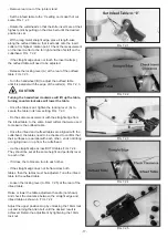
- Turn spring pin (A) approximately one-half revolution
clockwise and hold.
- Insert guard post into hole in table. Make sure spring pin
rests and places pressure against the table casting.
FIG. 5.6.
5.6 INSTALLING THE CUTTERHEAD GUARD
5.7 INSTALLING THE INFEED TABLE LEVER
(This part may have been pre-installed at the
factory.)
5.8 OUTFEED TABLE ADJUSMENT KNOB
- Locate the Infeed Table Lever and install into the
threaded hole of the Lifting Assembly under the Infeed
Table.
- Once the Infeed Table Lever is fully threaded into the
Lifting Assembly tighten the 19MM locking nut to secure
into position. FIG. 5.7.
- Locate the Outfeed Table Adjustment Knob, Allen Cap
Screw M6 x 12mm and 6mm Flat Washer.
- Insert the Outfeed Table Adjustment Knob onto the
square receiver of the Table Adjustment Screw Shaft
located under the Outfeed Table. Secure using the Allen
Cap Screw M6 x 12mm and 6mm Flat Washer. FIG. 5.8
5.5 DUST PORT ASSEMBLY
A Dust Port (A) is supplied with the jointer to help connect
it to a standard 4 inch vacuum hose.
Hardware needed:
M5 x 10 Phillips Head Screw (x4)
M5 Flat Washer (x4)
- Tighten the two upper Screws (B) with a Phillips
screwdriver, and tighten the two lower Screws (C) with
a Phillips screwdriver when the dust port is in proper
location. FIG. 5.5.
It is extremely important that a dust collection system
is used with this jointer to eliminate harmful airborne
dust, prevent the build-up of chips that may jam the
cutterhead, and to keep the working area clean of
debris. Make sure all connections are secure and
your dust collector is turned on before any milling of
lumber is done.
However, if you do not plan to use a dust collector,
then there is no need to attach this dust port to the
jointer. Chips ejected from the operating machine
should be collected and disposed of immediately to
keep the area clean and to avoid accidents.
FIG.5.5
FIG.5.6
FIG.5.7
FIG.5.8
CAUTION


