C
B
A
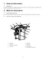
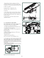
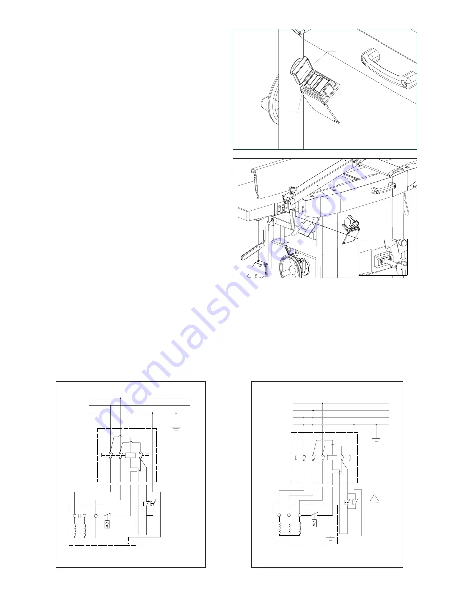
3.4. INSTALLATIONS OF LOOSE PARTS
H
G
FIG. 4
FIG. 5
3.4.1 SWITCH - INSTALLATION
- Fit the switch (G, Fig.4) onto the bracket with two hex nuts (H,
Fig.7)
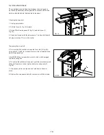
3.4.2 Cutterblock guard - INSTALLATION
- Take off both of the hex socket screws (A, Fig.5). Install the
cutterblock guard assembly (B, Fig.5) using two of hex socket
screws. Make sure the square washer (C, Fig. 5) stay between
the table and cutterblock guard.
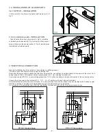
3.5 ELECTRICAL CONNECTION
Electrical installation should be carried out by competent, qualified personnel.
The mains connection should be made using the terminal box.
Ensure that the mains supply corresponds with that of the machine, use cables of a section suitable for the power of the motor. For a
supply tension of 400 V the minimum section recommended is 2.5 mm, including the earth wire.
For a mains supply of 230 V or a power rating greater than 15 A it will be necessary to increase the section of the connecting cables .
Connect the phase wires to the terminals R- S - T (L1 - L2 - L3) and the earth wire to the earth terminal.
On initial start-up check the direction of rotation, if it is incorrect then invert the two phase wires (for machines with 3 phase supply).
Direction of rotation of machines with single-phase supply is pre-determined during production .
On completion of the installation check that the terminal box is closed correctly and that the plug points are locked.
PE
N
34
44
b
33
43
a
L
OL
ON
OFF
Motor
Safty
switch
Y ell ow G re en
Bl ue
Br ow n
B la ck
Br ow n
B lu e
23
33
43
a
b
44
34
24
OL
ON
OFF
L1
PE
L3
L2
Motor
Safty
Switch
Y e ll o w G r e en
B l ue
B r ow n
Gr a y
B ro w n
Bl u e
B l a ck
PT310 Single phase
PT310 Three phase
-7-


