Sharpener Operator’s Manual
6. SUPPORT ARMS
A. INNER SUPPORT ARMS
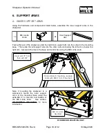
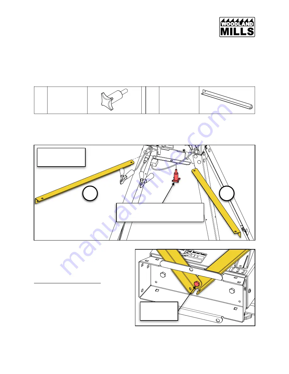
Using the hardware and components listed below, assemble the inner support arms to the
sharpener.
Facing the rear of the sharpener, slide the right inner support arm into the cutout in the mounting
base. Then slide the left support arm into the other cutout ensuring the left arm is below the
right arm. Secure both arms to the base and control box using the M6 4-lobe knob.
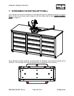
Note: If mounting the sharpener to a
workbench, fasten the inner support
arms to the mounting base using the
extra M6 X 14 mm hex bolt instead of
the M6 4-lobe knob. See section,
, for more
information.
1x
M6 4-Lobe
Knob
2x
Inner Support
Arm
BBS-MY2020-EN: Rev A
Page
of
18
52
19-May-2020
WORKBENCH MOUNTING ONLY
M6 X 14 mm
Hex Bolt
For workbench mounting, replace
knob with M6 X 14 mm hex bolt
Insert arm “
1
” first,
then arm “
2
”
1
2
Summary of Contents for BANDSAW BLADE SHARPENER
Page 1: ...BANDSAW BLADE SHARPENER OPERATOR S MANUAL BBS MY2020 EN Rev A Publication Date 19 May 2020 ...
Page 2: ......
Page 47: ...Sharpener Operator s Manual CONTROL BOX BBS MY2020 EN Rev A Page of 45 52 19 May 2020 ...
Page 48: ...Sharpener Operator s Manual GRINDING HEAD BBS MY2020 EN Rev A Page of 46 52 19 May 2020 ...
Page 51: ...Sharpener Operator s Manual NOTES BBS MY2020 EN Rev A Page of 49 52 19 May 2020 ...
Page 52: ...Sharpener Operator s Manual BBS MY2020 EN Rev A Page of 50 52 19 May 2020 ...
Page 53: ...Sharpener Operator s Manual BBS MY2020 EN Rev A Page of 51 52 19 May 2020 ...
Page 54: ...Sharpener Operator s Manual BBS MY2020 EN Rev A Page of 52 52 19 May 2020 ...
Page 55: ......
Page 56: ......

