background image


54 


2)


Lipid is  heterogeneous, the absorbance difference between the compared  cuvette and the 

reagent cuvette is easier to exceed the threshold. 

3)


Icterus is very similar to haemolysis but it is not easy to appear 0211 unless it is very serious 

4)


Samples that cannot be tested by 0210 will get error 0211. When blood flows through the 

sample flow channel, it doesn't flow through directly at one time, resulting in the error code. 

5)


In addition, the slight 0210 will appear that a part of the mixed liquid flows into the reagent 

hole first and then the other blood sample flows again a short time later. It means that there 

is a sample that does not pass through the channel in the high-speed centrifugal stage at the 

front. The subsequent centrifugation process starts again so there is an interval between the 

time  of  the  different  reagent  holes.  If  the  deviation  of  the  absorbance  of  the  compared 

cuvette and the reagent cuvette is greater than the threshold but the result of setting item 

also under the requirements, no error will be reported. 


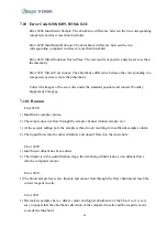
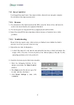
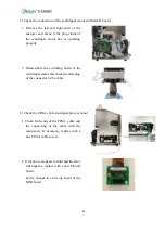
7.10.2 

Troubleshooting 

Please follow the steps in order. After each step is finished, retest whether the fault is cleared 

or not. If not, proceed to the next step. 

1)


Use a standard serum test. Stopping error reporting is a sample problem, otherwise please 

confirm uploading data and contact Woodley Equipment Company. 

7.11


Error Code 0212 

Disc Expired 


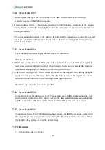
7.12


Error Code 0213 

Temperature Fault: 

1)


The temperature does not rise to 36°C when it finishes mixing . 

2)


The temperature exceeds 37 ± 1 

℃ 

during testing. 


7.12.1


Reasons 

1)


The temperature of the environment when the analyser is running does not meet the 

requirement of 10-30°C . 

2)


The cooling fan behind the analyser needs to be cleaned. 

3)


Temperature inaccuracy due to the temperature sensor connection problem. 


7.12.2


Troubleshooting 

Please follow the steps in order. After each step is finished, retest whether the fault is 

cleared or not. If not, proceed to the next step. 

Summary of Contents for InSight V-CHEM

Page 1: ...Veterinary Chemistry Analyser Service Manual...

Page 2: ...Unpacking Inspection 17 2 3 Analyser Specifications and EnvironmentalRequirements 17 2 4 Equipment Installation 18 2 4 1 Installation Requirements 18 2 4 2 Power Supply Connection 18 2 4 3 Analyser S...

Page 3: ...r Code 0107 37 7 5 1 Reasons 37 7 5 2 Troubleshooting 38 7 6 Error Code 0108 46 7 6 1 Reasons 46 7 6 2 Troubleshooting 46 7 7 Error Code 0109 49 7 8 Error Code 0202 0203 49 7 8 1 Reasons for Error 020...

Page 4: ...eshooting 66 7 20 Error Code 0302 66 7 20 1 Reasons 66 7 20 2 Troubleshooting 66 7 21 Error Code 0303 67 7 21 1 Reasons 67 7 21 2 Troubleshooting 67 Section 8 Hardware Malfunction and Troubleshooting...

Page 5: ...9 2 Troubleshooting 72 8 10 Wi Fi Cannot be Found 73 8 10 1 Reasons 73 8 10 2 Troubleshooting 73 8 11 Wi Fi Cannot be Connected 73 Section 9 Software Malfunction and Troubleshooting 74 9 1 Black Scree...

Page 6: ...ting 77 10 4 Reference Range on the Analyser and DMP is Inconsistent 77 10 4 1 Reasons 77 10 4 2 Troubleshooting 77 10 5 Report Standard Expression Error when DMPStarts 78 10 5 1 Reasons 78 10 5 2 Tro...

Page 7: ...orimetric cuvettes placed around the disc The polycarbonate film is used as the encapsulation For chemical analysis blood samples lithium heparin anticoagulant whole blood lithium heparin anticoagulan...

Page 8: ...mical reaction is stored in the QR code on the package of the reagent disc When the test is complete the test results are displayed on the screen The results report includes the test results of each i...

Page 9: ...3 Back View Right View...

Page 10: ...otential risk of infection all samples quality control products related containers and used reagents should be treated according to the corresponding biosafety level Medical instruments for in vitro d...

Page 11: ...Products should be stored in the original packaging box and maintained by the original protective packaging The storage environment should be moisture proof dustproof shock proof and corrosion proof...

Page 12: ...agent disc the centrifugation and detection process of microfluidic chip temperature control exposure of light source data acquisition and processing 2 Electric Control Modules The circuit logic contr...

Page 13: ...r heating film and temperature sensor Top film Bottom Function Control the chamber temperature at 37 0 2 C in order to make the chemical reaction at a constant temperature 2 Optical Module It includes...

Page 14: ...xenon lamp exposure emits a stroboscopic beam After the sample cuvette is absorbed through the test disc it enters the detection section The detector converts the optical signal into the measurable po...

Page 15: ...control board Main I and Main II board The functions are as follows 1 Power Supply Board Provide various voltage power supply for the instrument It mainly includes 24V driving centrifugal motor drawe...

Page 16: ...ed to the Main II board through the motor transfer board card and the motor signal is acquired and controlled Interactive Path of External Data External data passes through each port USB LAN port etc...

Page 17: ...ouch Step 3 2 The debugging function is mainly used to assist the operator in diagnosing the status and fault of the equipment The specific operation method is as follows 1 Enter the Main Interface an...

Page 18: ...lect Page Down 3 Continue to press the Page Down button 4 On the last page press the bottom left corner on the screen for more than 2 seconds 5 The hidden buttons Debug Default Parameter Default will...

Page 19: ...rive motor and centrifugal motor Press Open put in a new disc or any tested disc then press Close Wait until the drawer is completely closed then press Motor Start up The number shows on the Motor Spe...

Page 20: ...form The numbers are numerically transformed by the light refracted on a mirror in the ring edge of the reagent disc and the largest one is at 650 with 30 bias This function can be used to inspect wh...

Page 21: ...asing the IR value in step 7 maximum 255 cannot adjust the maximum value in 30 data near 650 30 diagnosis of the LED should be made with this function Touch LED Test and automatically acquire data If...

Page 22: ...mainly used for analysers that need to be restored after inadvertently modifying the parameters of the analyser 1 Select the hidden Parameter Default function 2 Press the analyser will automatically...

Page 23: ...e is found do not open the case Contact Woodley Equipment Company 2 2 Unpacking Inspection Please handle the analyser with care Check the contents of the package according to the packing list If items...

Page 24: ...f the power adaptor into the power jack at the rear of the analyser then plug the AC connector end of the power adaptor into the mains socket the mains socket is required to be grounded The plug end o...

Page 25: ...ser reaches the standby temperature the system will enter the main interface automatically and the screen will be displayed Note Under normal room temperature the time for the analyser to reach standb...

Page 26: ...off the analyser by clicking the button on the main interface and click the button to shut down the analyser as shown on the screen 2 Finally turn off the power switch at the front of the analyser to...

Page 27: ...cord from the back of the analyser 2 Open the fan cover and remove the black mesh filter 3 Wash the filter sponge with water and dry completely 4 Place the clean filter sponge back and tighten the fan...

Page 28: ...ethanol and a light source The specific steps are as follows 1 Using the debugging function control the drawer so it remains open the Open function in the Motor Test of the Settings function 2 Keeping...

Page 29: ...an connect to the network through Wi Fi and hotspot or other similar resources The specific steps are as follows 1 Turn on the analyser and on the Main Interface choose the Settings function 2 Choose...

Page 30: ...Woodley Equipment Company who will send you the software upgrade which you can then copy onto a USB flash drive Plug in the USB in the port at the rear of the analyser then press Analyser to show the...

Page 31: ...5 2 Create a folder called updatesoft on the USB 3 Copy InSight_V_Chem_arm 7z into the updatesoft folder 4 Insert the USB into analyser s USB port and then turn on the power 5 Press the Settings butto...

Page 32: ...26 6 Choose Analyser 7 Press Update 8 After the update has finished the screen should show Updated successfully then confirm 9 The analyser will restart automatically...

Page 33: ...r an inserted disc shows an error code When uploading data you should first select the most stable data transmission mode you can search the corresponding network or hotspot in the Wi Fi interface as...

Page 34: ...the signal resource with the corresponding signal to connect 4 Input the password of the account 5 After a successful connection Connected will be displayed 6 Select the return button select the Anal...

Page 35: ...29 7 Enter the information interface of the analyser Click the Upload button and wait for the instrument to upload an error message 8 After a few minutes the screen will show Updated successfully...

Page 36: ...e shipment If there is a problem with the touchscreen components accuracy the operator may recalibrate the screen 1 Enter the Main Interface select and enter the Settings interface 2 Select Screen Cal...

Page 37: ...ng the calibration operation e g there is an inaccurate touch of the red mark stop pressing the screen After more than 5 seconds the touchscreen calibration software will be cancelled automatically Th...

Page 38: ...according to an accurate quality control when some analytes results of some reagent batches is deviated The specific steps are as follows 1 Open the analyser and choose Settings 2 Select Page Down 3...

Page 39: ...odify 7 Change the coefficient of the specific item For example if you want to reduce it to 98 of the original detection value you only need to input 0 98 directly If you want to enlarge the result to...

Page 40: ...the TP given a wrong coefficient of 2 you can input 0 5 the reciprocal of 2 as a new factor to change and press Save Notice After you make a save all the coefficient will change to 1 as a basic numbe...

Page 41: ...red Inner hexagon spanner of 2mm Pointed pliers and side cutting pliers Box spanner of 5mm Hot melt glue heater and glue stick Alcohol more than 95 Thin tipped tweezers Scissors Pointed pliers and sid...

Page 42: ...36...

Page 43: ...and if this problem occurs please contact Woodley Equipment Company 7 4 Error Code 0105 AD AD Fault Transformation Fault Usually due to AD conversion chip damage no conversion signal output This error...

Page 44: ...number is lost If it is lost copy the config bin file and restart the device The config bin file can be acquired from Woodley Equipment Company 1 Enter the main interface select and enter the Settings...

Page 45: ...ram and make the serial number recover 2 Wipe the optical lens 1 Use the Open of debugging function to open the drawer of the analyser 2 Use a swab dipped in the alcohol to clean the optical lens The...

Page 46: ...in focusing on xenon lamp exposure control line and FPGA cable 1 Remove the inner hexagon screws on the back of the analyser as shown in the image 2 Remove two screws on the upper panel 3 Take off th...

Page 47: ...anhydrous ethanol to wipe the conductor pins of the cable then plug back into the analyser and restart the machine 5 Replace xenon lamp exposure control line 1 Confirm the model of the xenon lamp chan...

Page 48: ...42 6 After restarting test if the xenon lamp is flashing in the debugging interface Connect the lamp externally to test If the xenon lamp is not flashing replace the xenon lamp and optical assembly...

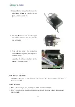
Page 49: ...th the lamp proceed with the following steps 2 Remove two screws from the bottom of the front panel As shown in the figure 3 Remove two screws at the front of the front panel As shown in the figure Re...

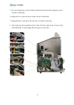
Page 50: ...the figure 6 Unplug the five connectors shown in the red circle in the figure 7 Unplug the three connectors in the red circles as shown in the figure 8 After taking out the temperature sensor in the...

Page 51: ...the bottom of the drawer 10 Take out the switching board and remove the motor connecting wire 11 Disassemble four screws at the bottom of the machine as shown in the figure 12 Take out the mechanical...

Page 52: ...ment Company 7 6 Error Code 0108 Location LED Abnormal Change the channel 1 for IR acquisition and the collected value is compared with the default IR threshold When the attenuation is more than 1 3 a...

Page 53: ...x default value If the deviation is greater than 500 it is abnormal 1 Using the debugging function to test the LED 2 Press LED Test and get the result to compare with the Factory Default If the differ...

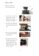
Page 54: ...pins 3 Use pliers to remove the glue on the surface of the LED and remove the LED from the fixed hole 4 Press a new LED to the bottom of the fixed hole and use the AB glue to attach the LED 5 Insert...

Page 55: ...g beyond the range of temperature that the analyser can operate properly This causes irregular temperature changes in the cavity of the lamp which leads to unstable output of the light source The xeno...

Page 56: ...move smoothly 2 The drawer control wire with motor is loose at the signal plug resulting in a false signal connection 3 Drawer drive gear is damaged resulting in abnormal transmission 7 8 2 Troublesho...

Page 57: ...ound when the drawer drive motor is working If there is any abnormal sound it may be caused by interference of components or damage to the drawer drive motor It is necessary to adjust or replace the d...

Page 58: ...ween Main I and Main II board are not synchronised There is a connection problem between the centrifugal motor and the Main II board 1 Push out the drawer slowly with both hands Avoid breaking the dri...

Page 59: ...Company 7 10 1 Reasons Error 0208 1 Insufficient sample volume 2 The sample does not flow through the sample channel clotted sample etc 3 At the sample adding port the sample is thrown out resulting i...

Page 60: ...e of the compared cuvette and the reagent cuvette is greater than the threshold but the result of setting item also under the requirements no error will be reported 7 10 2 Troubleshooting Please follo...

Page 61: ...over and pull out or use a pair of tweezers to open it 2 Remove the air filter sponge for cleaning or replacement 2 Check that the temperature shown on the temperature sensor is consistent with the am...

Page 62: ...56 2 Use a soldering iron to weld a new temperature sensor to the Main II board at the marked place in the figure Use AB glue to stick down the temperature sensor...

Page 63: ...board Screw down the four screws as shown in the figure Remove the Main I board If there is hot melt glue at the connector it can be removed easier by applying alcohol 2 Remove all the connection wire...

Page 64: ...13 2 Troubleshooting Please follow the steps in order After each step is finished retest whether the fault is cleared or not If not proceed to the next step 1 Upload the error data for diagnostics 1 C...

Page 65: ...pacers at the front of the LED Then increase the IR value Press the IR Setting and then Save to make the change of the IR active 3 Check the FPGA cable and plug connections If the problem cannot be so...

Page 66: ...tching board of the centrifugal motor and check the clamping of the connector to the cable 6 Check the FPGA cable and signal process board 1 Check both ends of the FPGA cable and the connecting of the...

Page 67: ...f light when the actual detection occurs after the liquid is evaporated causing the light intensity to exceed the circuit range 2 The virtual welding of the circuit causes a problem in the magnificati...

Page 68: ...l 1 Enter the debugging function and choose the temperature test and observe the temperature value on the screen If it is normal the value should be under 36 C 2 If the temperature sensor is broken re...

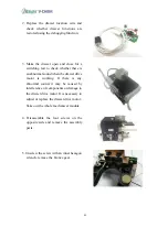
Page 69: ...e on the exposure control board 3 Unplug the xenon lamp and location connect wire from the exposure control board 4 Disassemble the four screws on the exposure control board 5 Unscrew the four nut col...

Page 70: ...ode 0225 Lower heating film fault Check whether the voltage of the lower heating film is normal when the voltage is loaded to the heating film the voltage drop on the dividing voltage resistance shoul...

Page 71: ...g wire of the heating film then replace it with a new one Assemble the whole parts back to the analyser in reverse format 7 19 Error Code 0301 FPGA Fault Hardware 1 cannot start or cannot receive the...

Page 72: ...Replace the Main II board 5 Replace the Main I board 7 20 Error Code 0302 Scan Module Fault Scan module cannot be connected 7 20 1 Reasons 1 External barcode scanner is not connected 2 Built in scanni...

Page 73: ...chip is poorly soldered resulting in failure to read normal data 2 There is a problem with the Main II board circuit board causing abnormalities such as power supply 3 The data connection cable of th...

Page 74: ...After each step is finished retest whether the fault is cleared or not If not proceed to the next step 1 Check whether the power plug is plugged in tightly 2 Replace the adaptor to test for adaptor fa...

Page 75: ...if the problem can be solved If it is valid then change a new panel directly 6 Replace the power supply board refer to section 7 17 8 2 White Screen BIOS Cannot Start The screen displays white after s...

Page 76: ...ectory of the USB flash disc Plug in the USB flash disc to restart the device 8 4 Blurred Screen Part of the display gradually disappears The screen is blurred or screen colour display is abnormal 8 4...

Page 77: ...ogram error 3 Power strip failure 8 6 2 Troubleshooting Please follow the steps in order After each step is finished retest whether the fault is cleared or not If not proceed to the next step 1 Check...

Page 78: ...of the USB flash disc Plug in the USB flash disc to restart the device 8 8 System Does Not StartProperly The equipment cannot start up normally after being powered on Check whether the power cord plug...

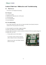
Page 79: ...signals 8 10 1 Reasons 1 Wi Fi cable is disconnected 2 Wi Fi module is broken 8 10 2 Troubleshooting 1 Re plug the Wi Fi antenna and test the signal strength 2 If it cannot be solved replace with a n...

Page 80: ...ain program causes the device not to start 9 2 1 Reasons 1 Some library files are damaged or lost which makes it impossible to start the program 9 2 2 Troubleshooting 1 Restart the device and continue...

Page 81: ...Woodley Equipment Company 9 4 Reference Ranges are Inaccurate After the upgrade procedure the reference range units both SI standard units and Common standard units seem inaccurate 9 4 1 Reasons The...

Page 82: ...re is no network connection or network disconnection during the chemical analysis of the device which causes the data of the device to fail uploading to the server thus the data cannot be synchronised...

Page 83: ...ement platform software resulting in inconsistent equipment and management platform 2 For recently modified reference ranges of some parameters equipment that has already been manufactured will not ye...

Page 84: ...a Printing data results in garbled or serial data 10 6 1 Reasons 1 The device software version does not match the management platform software version 2 Software bug When the software is printed if tw...

Page 85: ...an Error of Data Source ODBC Error popping data source during use 10 8 1 Reasons 1 No driver files or missing drive files in the computer system 10 8 2 Troubleshooting 1 Please contact our Woodley Eq...

Page 86: ...ntensity of the analyser detection wavelength is abnormal Na reports The test result is incorrect or a negative value Reasons 1 An abnormal blood sample results in an incorrect result 2 The intensity...

Page 87: ...81 Result appear The test item detection exceeds the lower limit Reasons 1 An abnormal blood sample results in an incorrect result 2 The intensity of the analyser detection wavelength is abnormal...

Page 88: ...82 Old Station Park Buildings St John Street Horwich Bolton BL6 7NY UK Tel 44 0 1204 669033 Email sales woodleyequipment com Web www woodleyequipment com...

Reviews: