2 Instrument Configuration
Copyright © WOODLEY EQUIPMENT COMPANY LTD.
56
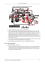
2. Smell. Power problems may burn out some components; an acrid smell can suggest a burnout.
Do not power on in this case.
3. Touch. Power on and touch the corresponding component on the main control panel by hand. If
the temperature feels abnormal, the component could be broken.
4. Test. The first three steps can be used to identify power overload problems on the main control
panel. Step 4 is designed for determining what has malfunctioned. Testing can also identify the
problem of circuit breakage. This step is also part of maintenance. A multimeter is used to test for
power problems.
Common Problems Found in Main Control Panel Maintenance and their Indicators
See the following table for details.
Problem
Description
Problem Indicators
Solution
Analogy power
input of -12V is not
loaded, and the
device power
supply is switched
into auto protection
mode when
powered on.
The power indicator light D19 is not
activated.
This issue is mostly caused by the
fact that the analog power input of
-12V has shorted out. Another
possible reason is the breakdown
of the polar capacitors (mostly
tantalum capacitors here). Due to
the abundance of -12V networks,
users are recommended to
replace the motherboard. The
damaged components can be
located by PCB for replacement
by qualified maintenance
personnel.
Analogy power
input of +12V is not
loaded, and the
device power
supply is switched
into auto protection
mode when
powered on.
The power indicator light D18 is not
activated.
This issue is mostly caused by the
fact that the analog power input of
+12V has shorted out. Another
possible reason is the breakdown
of the polar capacitors (mostly
tantalum capacitors here). Due to
the abundance of +12V networks,
users are recommended to
replace the motherboard. The
damaged components can be
located by PCB for replacement
by qualified maintenance
personnel.

