2 Instrument Configuration
Copyright © WOODLEY EQUIPMENT COMPANY LTD.
62
2.4 Optical System
2.4.1 Integral Replacement of the Optical Assembly
Purpose
The optical assembly can be disassembled and replaced by following the procedures specified in
this section; however, in each case,
Preliminary Steps
need to be taken before you begin.
Tools/Spare Parts
⚫
#2 (Ph2) Phillips screwdriver
⚫
Medical syringe attached to a silicone tube
⚫
Optical components that have passed tuning tests
Preliminary Steps
1. Turn off the power switch on the left side of the device.
2. Pull out the power cord plug from the rear panel of the device.
3. Open the right-side door and disassemble the top cover panel.
Disassembly
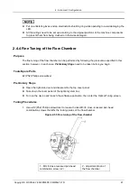
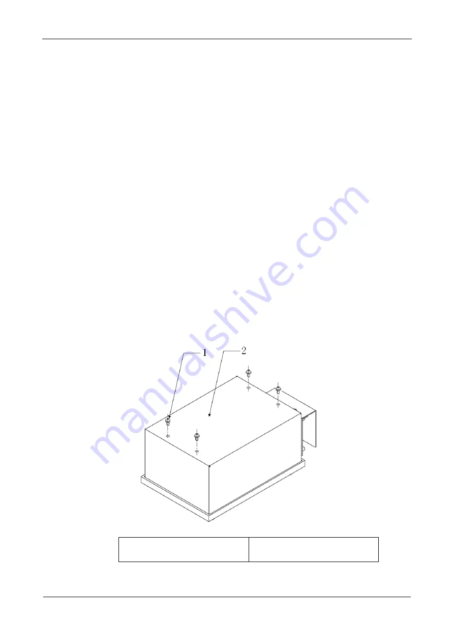
1. Use a #2 (Ph2) Phillips screwdriver to disassemble the four M3×8 cross-recessed pan-head
combination screws which affix the cover panel of the optical system, and carefully detach it.
1 - M3×8 cross-recessed pan-head
combination screw (×4)
2 - cover panel of the optical system


