background image

This  stove  is  approved  for  mobile  home  installa-

tion  in  the  USA  only  (DO  NOT  INSTALL  IN  MOBILE 
HOMES  IN  CANADA).  In  addition  to  the  installation 
and safety instructions, the following requirements are 

MANDATORY

 for installation in a mobile home. All mo-

bile home installations must be made in accordance to 
Manufactured Home and Safety Standard (HUD), CFR 
3280, part 24.

1.  The stove must be permanently bolted to the 

ƀQQT

to prevent movement of the stove.  Movement of 
the stove could separate the outdoor air connection 
and/or chimney connection and create an unsafe 
operating condition.. Examine 

ƀ

oor structural mem-

bers to make sure that the weight of the installation 
can be supported.

2. 

CAUTION: THE  STRUCTURAL  INTEGRITY  OF 
THE MOBILE HOME FLOOR, WALL, AND CEIL-
ING/ROOF MUST BE MAINTAINED.

3.  The  stove  must  be  electrically  grounded  to  the 

steel frame of the Mobile Home. The stove must be 
grounded using a #8 ga. ground wire with approved 
termination and star washer.

4.  The 

ƀ

oor protection and speci

ſ

ed clearances noted 

elsewhere in this manual must be maintained.

5.  The  unit  must  have  a  permanent  outside  ai   

r

source  for  combustion.  The  combustion  air 
intake  system  must  be  of  metal  construction. 
Minimum  diameter  for  the  intake  ducting  is  4
inches.   The  air  intake  must  be  screened  to  pre-
vent  the  entrance  of  rodents.    The  outside  air 
inlet  must  be  kept  free  of  leaves,  snow,  ice,  or 
other  debris  that  could  restrict  air  supply  when 
the appliance is in operation. 


6.


WARNING:  DO  NOT  INSTALL  IN  A  SLEEPING 
ROOM.

7. 

WARNING: DO NOT USE SINGLE WALL CON-
NECTOR PIPE ANYWHERE IN A MOBILE HOME


INSTALLATION.

  A  listed  double-wall  chimney 

connector  system,  ceiling  thimble,  roof  thimble, 
spark arrestor, and roof 

ƀCUJKPI

 suitable for use in 

Mobile Homes must be used. All components of the 
chimney and connector system must be of the HT 
type and listed to UL 103 HT. Install per chimney 
manufacturer’s instructions.

8.  The openings in the chimney cap must not permit 

the entr

CPEGQHCŊOOFKCOGVGTTQF

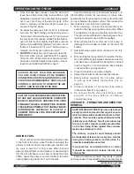
9.  If the chimney exits the Mobile Home at a location 

other than through the roof, and exits a point 7 ft. 

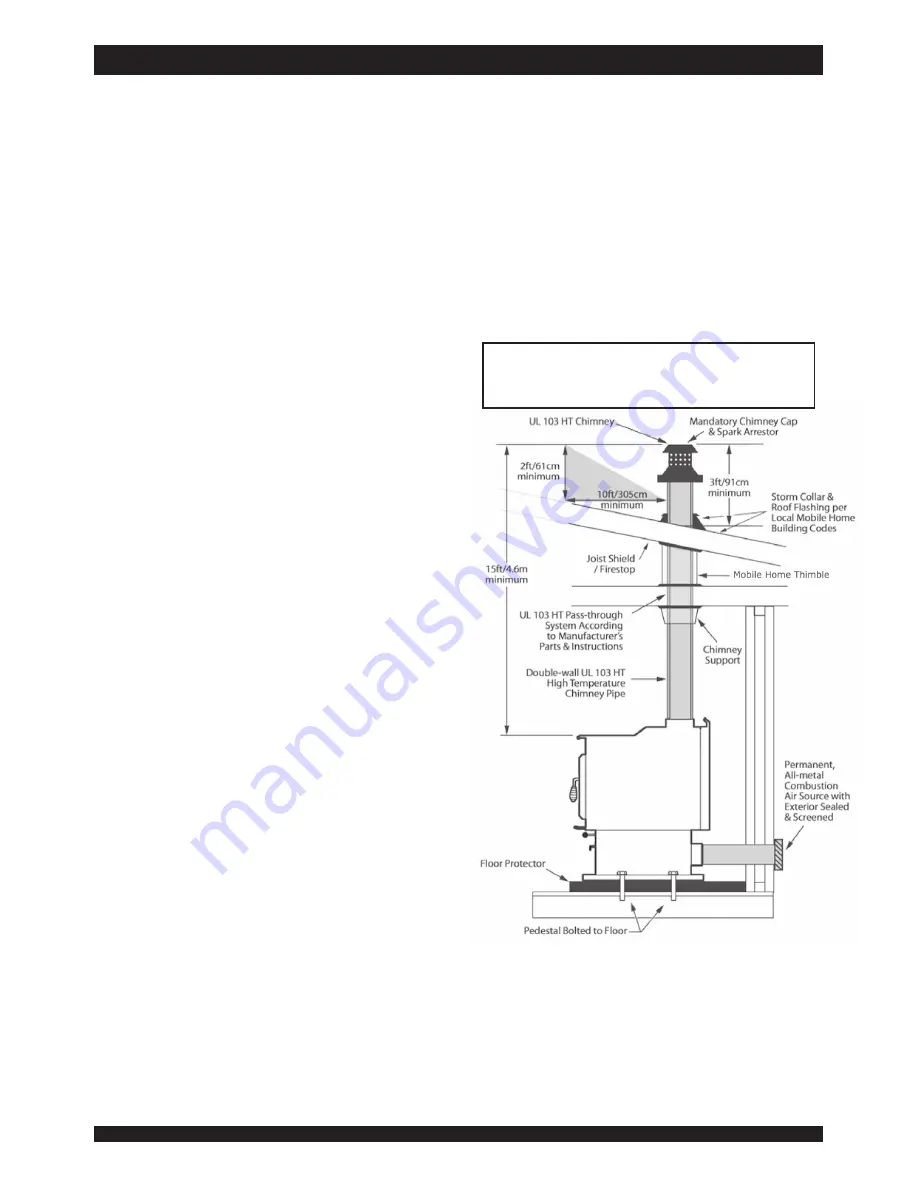
)LJXUHăRPH,QVWDOODWLRQ

/ 2.13m or less above the ground upon which the 
Mobile Home is set upon, a guard shall be 

ſVVGF

 at 

the point of exit up to 7 ft./2.13m.

10.  The chimney shall be attached directly to the room 

heater and shall extend at least 3 ft./91.4cm above 
the part of the roof through which it passes. The top 
of the chimney must project at least 2 ft./60.1cm 
above the highest elevation of any part of the Mobile 
Home within 10 ft./3.1m of the chimney.

11.  Use  h i g h - t e m p e r a t u r e   silicone  to  seal  at 

the  location  where  the chimney  and  fresh  air   
supply  system  penetratesthe exterior of the
 structure. 

12.


The  chimney  system  must  comply  with  all  local 
fire codes and governmental requirements.

13. Stove must be tightly secure to the floor and not 

move if lateral force is applied.

    WoodPRO™


02%,/(+20(,167$//$7,21,16758&7,216

DO NOT USE ANY URETHANE FOAM

SEALANTS TO FILL VOIDES OR CRACKS 

AROUND THE STOVE PIPE

12

Summary of Contents for WS-TS-1500

Page 1: ...www woodprostoves com 1 877 427 3316 WS TS 1500 WS TS 2000 WS TS 2500 www woodprostoves com www woodprostoves com 4085 112 Rev A ...

Page 2: ...ECT A WOOD BURNING STOVE TO AN ALUMINUM TYPE B GAS VENT This is not safe Use code approved masonry chimney with flue liner or a manufactured Underwriters Laboratories Listed UL 103 HT US ULC S629 CAN Residential Type and Building Heating Ap pliance Chimney Use a 6 152mm diameter chim e e S t f a r d d o o g a e v i g o t h g u o n e h g i h s i t a h t y e n specifics in Chimney Connections instruc...

Page 3: ...ing the fire 27 When adding fuel be careful not to smother the fire Do not build fires against glass and do not load fuel to a height or in such a manner that it creates a hazard when opening the door 28 NEVER LEAVE THE STOVE UNATTENDED with door open Always close the door after ignition 29 DO NOT CONNECT TO OR USE IN CONJUNC TIONWITH ANY AIR DISTRIBUTION DUCTWORK UNLESS SPECIFICALLY APPROVED FOR SUC...

Page 4: ... SERVICE HINTS Preventing Creosote Buildup 20 Chimney Draft 20 21 Glass Care Replacement 21 Door Gasket Replacement 22 BLOWER MAINTENANCE WIRING DIAGRAM 31 BAFFLE REMOVAL 23 24 FLOOR PROTECTOR CALCULATIONS 32 CHIMNEY STOVE MAINTENANCE LOG 33 WARRANTY 34 35 CUSTOMER SERVICE INFORMATION 36 MINIMUM CLEARANCES with SINGLE WALLED PIPE MINIMUM CLEARANCES ALCOVE and DOUBLE WALLED PIPE 6 LOCATING THE STOV...

Page 5: ...red utilizing either a recently cleaned and inspected 6 152mm lined masonry chimney or a 6 152mm i d manufactured chimney system listed to UL 103 HT US ULC S629 CAN 5 Use round 6 152mm dia minimum 24 MSG black or 26 MSG blue steel stove pipe to connect the stove to the chimney Do not use galvanized stove pipe NOTE Mobile home installations require double wall UL 103 HT high temp connector pipe Sec...

Page 6: ...6 Minimum Clearances for installation according to UL 1482 US ULC S627 CAN A ...

Page 7: ...7 Top A A Alcove ...

Page 8: ...philips BLOWER ATTACHMENT 8 4 places A GASKET ...

Page 9: ...9 WS TS 2500 23 8 6 ...

Page 10: ...10 6 ...

Page 11: ...any condensation in the flue to run back into the firebox 2 Horizontal pipe runs must slope upwards towards the chimney at least 1 4 6 4mm per foot of horizontal run 3 You must have at least 18 457mm of clearance between any horizontal piping and the ceiling 4 The pipe cannot extend into the chimney flue figure 8 5 Secure all pipe elbow sections with three 3 equally spaced sheet metal screws at each ...

Page 12: ...trict air supply when the appliance is in operation 6 WARNING DO NOT INSTALL IN A SLEEPING ROOM 7 WARNING DO NOT USE SINGLE WALL CON NECTOR PIPE ANYWHERE IN A MOBILE HOME INSTALLATION A listed double wall chimney connector system ceiling thimble roof thimble spark arrestor and roof ƀCUJKPI suitable for use in Mobile Homes must be used All components of the chimney and connector system must be of t...

Page 13: ...ed for proper drafting to prevent back puffing smoke spillage and to maximize performance Gauges to measure draft are readily available at stove stores and are economical to rent or purchase Factors such as wind barometric pressure trees terrain and chimney temperature can have an adverse effect on the draft The manufacturer cannot be held responsible for external factors leading to less than optim...

Page 14: ...VAC supply stores You may wish to view chimney manufactur ers information on line See www duravent com www selkirkinc com or www mtlfab com VENTING TO EXISTING FIREPLACE In some instances people desire to convert an existing fireplace for stove use Usually safe connec tion to an existing masonry chimney requires more work than using a prefabricated chimney The existing fireplace must be closed and s...

Page 15: ...ller 1 An entry hole must be cut through the masonry and tile liner with minimal damage to the liner At least Figure 14 Fireplace Conversion 8 203mm of liner must remain below the entry position When locating the stove and stovepipe all minimum clearances must be observed from com bustible surfaces including mantels combustible trim work ceilings and walls Positioning the center of the stove pipe ...

Page 16: ...be covered and thimble supported with a sheet steel support minimum 24 gauge in thickness D Chimney Section Pass through Solid insulated listed factory built chimney length with an inside diameter 2 51mm larger than the chimney connec tor and having 1 25 4mm or more of insulation serving as a pass through for a single wall sheet steel chimney connector of minimum 24 gauge thickness with a mini mum...

Page 17: ...ency of the stove and reduces chimney emissions Smoke given off by burning fuel consists of very small organic liquid droplets If these droplets condense they form a sticky tar like substance called creosote When operated properly this stove is designed to burn these droplets Burning these droplets releases heat that would otherwise be lost up the chimney as smoke Following the instructions below ...

Page 18: ...TEMP PAINT WHICH REQUIRES A SERIES OF BURNS TO CURE THE PAINT FOR DURABILITY AND A LIFETIME OF SERVICE Proper curing of the high temp paint requires a series of three initial burns The stove should be allowed to cool off between each burn The first two burns should be small fires and low temperatures 250 F 120 C for a duration of 20 minutes each The third fire should be at a medium high temperatur...

Page 19: ...y but should be kept 1 2 25mm 50mm below the secondary air tubes Also position the fuel to leave space so the air from the inlet can work between the pieces of fuel This reduces the time it takes for new fuel to burn properly 1 When refueling increase the center primary air control to the fully open pulled out position When fire brightens slowly and carefully open the door This procedure will preve...

Page 20: ...20 ...

Page 21: ...21 ...

Page 22: ...nd will need to be replaced Inspect glass and door gaskets periodically to ensure proper seal if gaskets become frayed or worn replace immediately DOOR GASKET REPLACEMENT CAUTION DO NOT OPERATE A STOVETHAT IS MISSING DOOR GASKET MATERIAL OVER FIR ING AND UNSAFE OPERATING CONDITIONS MAY RESULT PROCEDURE 1 Ensure appliance is not in operation and is thor oughly cooled 2 Remove old door gasket and cl...

Page 23: ...23 BAFFLE REMOVAL ...

Page 24: ...24 BAFFLE REMOVAL ...

Page 25: ...SERVICE PARTS 25 ...

Page 26: ...SERVICE PARTS 26 ...

Page 27: ...SERVICE PARTS 27 ...

Page 28: ...SERVICE PARTS 28 ...

Page 29: ...SERVICE PARTS 29 ...

Page 30: ...SERVICE PARTS WS TS 2500 30 ...

Page 31: ... free of dust and dirt NOTICE ANY REPLACE MENT WIRING MUST HAVE EQUIVALENT INSULA TION AND TEMPERATURE RATING 105 C CAUTION MOVING PARTS CAN CAUSE INJURY DO NOT OPERATEWITH COVER REMOVED DANGER SHOCKHAZARD DISCONNECT POWERSOURCEBEFOREINSTALLATION AND WHENEVER SERVICING BLOWER ASSEMBLY BLOWER MAINTENANCE WIRING DIAGRAM 31 ...

Page 32: ...roposed material s b For multiple layers add R values of each layer to determine overall R value 3 If the overall R value of the floor protector system is equal to or greater than the floor protector specifications given the alternate is acceptable Definitions Thermal conductance C BTU W hr ft2 F m2 K Thermal conductivity k Btu inch W Btu hr ft2 F m K hr ft F Thermal resistance R ft2 hr F m2 K Btu W E...

Page 33: ...DATE OF SERVICE PERFORMED BY DESCRIPTION CHIMNEY STOVE MAINTENANCE LOG 33 ...

Page 34: ...Warranty WoodPRO Secondary tubes baffle gaskets Wood Firebox flue collar front door ash door 3 34 ...

Page 35: ...Warranty 35 ...

Page 36: ...36 www woodprostoves com 2 ...

Reviews: