background image

Rev 8.0/6-13 

27 

MRTALPCH6-DC: #35054 

A

IR 

F

ILTER 

M

AINTENANCE


(for in-line filters) 

Filter Function and Conditions Requiring Service 

This air filter prevents solid particles from contaminating components in the vacuum system. 

CAUTION:    Examine air filter regularly and empty when necessary. 

Open each filter regularly to determine whether liquid or other contaminants are trapped inside.   

Remove any liquid or contaminants found.    Clean or replace the filter element if it has an overall 

dirty appearance, or if there is a noticeable increase in the time required to attain full vacuum 
(see REPLACEMENT PARTS LIST). 

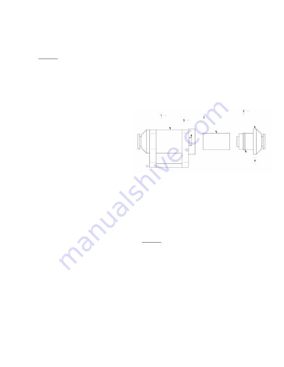
Filter Service Procedures 

1)  Hold the filter case (1) and turn the 

removable end (2) counter-clockwise 
approximately 45° until it stops 
moving. 

2)  Pull the end outward from the case 

and remove the filter element (3).   

Use an air hose or other suitable 
means to remove any liquid or other 
contaminants found inside the case.   

Also make sure the seal (4) is not damaged. 

3)  Determine whether the filter element needs to be replaced (see Conditions Requiring Service 

above). 

4)  Depending on the outcome of step 3, install a new element or reinstall the old element, as 

shown in the illustration. 

5)  Align the 2 projections on the removable end with the grooves in the case, and insert the end 

into the case.    Push in and turn the end clockwise approximately 45° until it stops moving.   

Make sure that the projections are completely visible through the windows (5) in the case. 

6)  Test the vacuum system, to make sure the air filter does not leak (see V

ACUUM 

T

EST


preceding).

Summary of Contents for Powr-Grip MRTALPCH610DCO

Page 1: ...e see serial label and record number here MANUAL ROTATOR TILTER LOW PROFILE DC VOLTAGE WITH DUAL VACUUM SYSTEM AND CHANNEL STYLE PAD FRAME READ ALL INSTRUCTIONS AND WARNINGS BEFORE OPERATING THIS LIFT...

Page 2: ......

Page 3: ...es 8 To Install Remove Pad Frame Extensions 9 INTENDED USE 10 LOAD CHARACTERISTICS 10 OPERATING ENVIRONMENT 11 DISPOSAL OF THE LIFTER 11 OPERATION 12 BEFORE USING THE LIFTER 12 Taking Safety Precautio...

Page 4: ...E CONTROL SYSTEM TEST 26 AIR FILTER MAINTENANCE 27 Filter Function and Conditions Requiring Service 27 Filter Service Procedures 27 VACUUM PUMP MAINTENANCE DYNAFLO DV1032102 28 Replacing the Diaphragm...

Page 5: ...to maintain vacuum Vacuum Gauges 2 dial gauges indicate current vacuum level in positive inches of Hg and negative kPa Vacuum Lift Light Green light is energized whenever vacuum is higher than the le...

Page 6: ...tly on the load prior to lifting see OPERATION TO APPLY THE PADS TO A LOAD Never lift a load when any vacuum indicator shows inadequate vacuum Never touch the vacuum release controls during a lift Thi...

Page 7: ...RY GAUGE 19 VACUUM GAUGE 2 BATTERY CHARGER 11 ENABLE BUTTON 20 ROTATION RELEASE LEVER 3 VACUUM RESERVE TANK 12 APPLY BUTTON 21 Cover for AIR FILTERS 4 Cover for BATTERY 13 RADIO RECEIVER optional 22 Q...

Page 8: ...Rev 8 0 6 13 6 MRTALPCH6 DC 35054 1 TRANSMISSION INDICATOR LIGHT 2 TRANSMITTER POWER ENABLE BUTTON 3 RELEASE BUTTONS 4 APPLY BUTTONS 5 EMERGENCY TRANSMITTER DISCONNECT OPTIONAL RADIO TRANSMITTER...

Page 9: ...applicable rated to carry the maximum load weight plus the lifter weight see SPECIFICATIONS Maximum Load Capacity and Lifter Weight Note Any application of the lifter must conform to all statutory or...

Page 10: ...o the vacuum pads located on the extensions WARNING Removing any extension or disconnecting the corresponding vacuum pad reduces load capacity of lifter To support smaller dimensions and weights the p...

Page 11: ...ion that is equipped with a control handle should be installed on the lower end of the pad frame ie when oriented vertically 3 Align the bolt holes in the pad frame extension with the bolt holes in th...

Page 12: ...of the load are determined by the Pad Spread see SPECIFICATIONS the maximum length and width are determined by the allowable overhang or the amount of load material that can extend sideways beyond th...

Page 13: ...ECIFICATIONS The lifter s work environment must be free of metal particles or any other contaminates that could damage lifter components through airborne contact or any other means of transmission in...

Page 14: ...ry energy before using lifter See MAINTENANCE BATTERY TEST Perform all inspections and tests required by the INSPECTION and TESTING SCHEDULES see MAINTENANCE In addition if the lifter has been in stor...

Page 15: ...System the operator can engage the lifter s apply and release functions at distances up to 250 ft 76 m provided there is a direct and clear view of the lifter and its status indicators from the opera...

Page 16: ...function see TO RELEASE THE PADS FROM THE LOAD to follow Note If the transmitter is activated the transmission indicator light flashes green when any button on the transmitter is pressed and held if...

Page 17: ...Other Surfaces When the lifter is attached to contaminated rough or porous load surfaces it may not be able to maintain a vacuum level in the green range on both vacuum gauges due to leakage in the s...

Page 18: ...monitored throughout the entire lift WARNING Vacuum indicators must be visible to operator throughout entire lift If the vacuum system experiences leakage while the lifter is attached to the load the...

Page 19: ...between the vacuum pads and the load Since the alarm may sound in such circumstances consult the section TO APPLY THE PADS TO A LOAD Vacuum Level on Other Surfaces to determine whether the lifter can...

Page 20: ...y other position WARNING Make sure load is positioned correctly on lifter see TO APPLY unbalanced loads may rotate unexpectedly when latch is disengaged Remember that the load is longer in its diagona...

Page 21: ...sition pull the tilt release lever to disengage the tilt latch Lift upward or press downward on the control handle to tilt the load as desired If load size permits maintain control with the handle thr...

Page 22: ...uld soil or damage the vacuum pads Use the hoisting equipment to gently lower the lifter onto a stable support then detach the hoisting equipment hook from the lift spool If the lifter is transported...

Page 23: ...ours use or whenever lifter is out of service for 1 month or more Examine the lifter s structure for visual damage Examine the vacuum system including vacuum pads fittings and hoses for visual damage...

Page 24: ...ICATIONS using an actual load or an equivalent simulation 13 Employ the following method to test with an actual load 1 Place a test load with appropriate LOAD CHARACTERISTICS see INTENDED USE on a sta...

Page 25: ...is not in stand by mode However the battery gauge shuts off temporarily while the vacuum pump is running to prevent an inaccurate reading When the pumping cycle is completed the battery gauge requires...

Page 26: ...ctioning correctly the energy reading should be higher when the charger is plugged in VACUUM PAD MAINTENANCE Friction Coefficient The friction coefficient represents the lifter s ability to resist loa...

Page 27: ...include soapy water and other mild cleansers Do not use solvents petroleum based products including kerosene gasoline and diesel fuel or any harsh chemicals for cleaning Do not use unauthorized rubber...

Page 28: ...er to verify that functions are being performed as intended If the Remote Control System does not function correctly review the following potential causes of malfunction and correct them as directed T...

Page 29: ...ovable end 2 counter clockwise approximately 45 until it stops moving 2 Pull the end outward from the case and remove the filter element 3 Use an air hose or other suitable means to remove any liquid...

Page 30: ...n the illustration Replacing the Gasket Flap Valves 1 Remove the four head screws 1 and lock washers 2 and remove the head assembly 3 7 2 Invert the head and remove the two valve plate screws 7 Remove...

Page 31: ...four head screws 1 and remove the head 2 2 Invert the head and remove the four valve plate screws 9 3 Lift out the valve plate 6 to access the exhaust valve flapper and head gasket 22 4 Remove the exh...

Page 32: ...o lift the maximum load weight If the pump and the warning buzzer do not turn on or the lift light does not turn off before vacuum decreases to a level lower than the minimum lifting level the vacuum...

Page 33: ...ain a lower vacuum level turn the screw clockwise To maintain a higher vacuum level turn the screw counter clockwise 2 Recheck the vacuum switch setting following each 1 6th turn of the adjustment scr...

Page 34: ...line for radio transmitter 2 64664 Battery 12 V DC 7 Amp Hours 1 64590 Battery Gauge 1 64460 Circuit Breaker 15 A 1 64453CP Circuit Board Populated 1 64271 Strobe Light 12 V DC Amber option 1 64238BA...

Page 35: ...use Repairs are required due to abnormal wear and tear The product has been damaged misused or neglected If a problem is not covered under warranty Powr Grip will notify the customer of costs prior to...

Page 36: ...Rev 8 0 6 13 34 MRTALPCH6 DC 35054...

Page 37: ...Rev 8 0 6 13 35 MRTALPCH6 DC 35054...

Page 38: ...Rev 8 0 6 13 36 MRTALPCH6 DC 35054...

Reviews: