


Operation
15
MAN1339
(05/17/22)
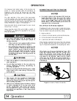
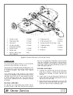
Mechanical Connection
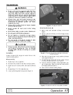
1.
Attach cutter using a 1-1/8" clevis pin and clip.
2.
Attach safety tow chain (25) to drawbar support.
Leave enough slack for turning.
3.
Connect cutter driveline to tractor PTO shaft, mak-
ing sure the spring-activated lock pin slides freely
and is seated in tractor PTO splined groove.
4.
Attach driveline shield tether chain to tractor draw-
bar to prevent rotation, if desired.
NOTE:
CV driveline does not require a tether chain.
5.
Loosen bolts in jack mount. Adjust jack so foot plate
sits flat for storage. Tighten bolts.
6.
Remove parking jack (16) from the tongue and at-
tach it to the storage post on the front of the left
wing.
Hydraulic Connection
1.
Inspect hydraulic hoses to ensure they are in good
condition.
2.
Clean the fittings before connecting them to the
tractor hydraulic ports.
3.
Route the hose through the hose holder at the hitch
and be sure the hose can slide freely in the holder.
Do not allow hose slack to drag on the ground or
become caught on tractor protrusions.
4.
Attach the hydraulic hose to the tractor.
5.
From the operator position, start tractor and raise
and lower deck several times to purge trapped air
from the hydraulic cylinder.
Interference Check
1.
Be sure that tractor 3-point lift links do not inter-
fere with hydraulic hoses, cutter driveline, or cutter
frame.
2.
Check for straight-ahead operation and at full turn-
ing angles. If there is any interference, remove the
lower lift links.
3.
Contact between tractor lift links and cutter parts
can cause damage, especially when turning.
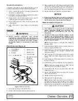
CV Driveline Turning Limits
■ You must not exceed a turning angle of 80 de-
grees at the head of the Constant Velocity
driveline or damage will occur.
NOTE:
Remove CV drive shipping bracket before
operation and discard. This bracket is only sup-
plied on factory assembled units with a CV drive
installed.
1.
To check for potential excessive turn angle, discon-
nect the driveline from tractor.
2.
Start engine and turn as far right or left as possible.
3.
Shut engine off and try to connect CV driveline to
tractor. If it cannot be connected, the turn angle is
too severe.
4.
Restart engine and straighten angle slightly, shut off
engine and try to connect CV driveline to tractor.
5.
Repeat the process until the driveline can be con-
nected. The point at which the driveline can be
connected is the maximum turn that should be
made.
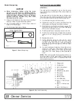
Cutting Height Adjustment
■ Avoid ground contact with blades. Striking
ground with blades produces one of the most
damaging shock loads a cutter can encounter. If
this occurs repeatedly, the cutter, driveline, and
gearboxes will be damaged.
Cutting height range is from 1" to 15". A hydraulic cylin-
der is used for cutting height adjustment.
When selecting a cutting height, you should consider
the area of operation. If the ground is rolling and has
mounds the blades could contact, set the cutting height
accordingly. The cutting height (blade edge) is approxi-
mately 1" above the bottom of the side skid.
Cutting Height (Normal Mowing) - Center Section
1.
Position the cutter on a hard level surface and se-
lect an approximate cutting height, example 6".
2.
Raise wings and lock them in the UP position.
3.
Raise or lower the center section to obtain a dis-
tance of 5" from bottom edge of skid shoe to the
ground.
4.
Loosen jam nuts on the attitude rod that runs from
the wheel yoke to the tongue.
5.
Adjust rod in or out until the rear of the cutter is ap-
proximately 1/2" higher than the front.
6.
Tighten jam nuts against sleeve.
Cutting Height (Normal Mowing) - Wings
1.
Lower wings to normal mowing position.
2.
Loosen the jam nut on the adjustable link (turn
buckle).
3.
Lengthening the link will raise the wing, shortening
the link will lower the wing. The rear edge of the
wing should be parallel to the ground.
When using the cutter to shred, the rear of the cutter
deck should be approximately 1/2" to 1" lower than the
front.
NOTICE
NOTICE


