


16 Operation
MAN1339
(05/17/22)
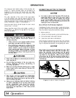
TRACTOR OPERATION
Use care when operating around tree limbs and other
low objects. Avoid being knocked off tractor and being
injured.
Only use a tractor with a Roll Over Protection Structure
(ROPS) and seat belt. Securely fasten seat belt.
The cutter is operated with tractor controls. Engage the
PTO at a low RPM to prevent excessive loads on the
cutter drive system. Increase throttle to recommended
PTO operating RPM.
Be sure operator is familiar with all controls and can
stop tractor and cutter quickly in an emergency. The
operator should give complete, undivided attention to
operating tractor and cutter.
CUTTER OPERATION
When beginning operation of the cutter, make sure that
all persons are in a safe location.
Power for operating the cutter is supplied by the tractor
PTO. Operate PTO at 540 (1000 RPM for “Q” models).
Know how to stop the tractor and cutter quickly in an
emergency.
Engage PTO at a low engine, RPM to minimize stress
on the drive system and gearbox.
With PTO engaged, raise PTO speed to 540 or 1000
RPM depending on model and maintain throughout
cutting operation.
Gearbox protection is provided by a slip clutch with re-
placement fiber disc. The slip clutch is designed to slip
when excessive torsional loads occur.
Move slowly into material. Adjust tractor ground speed
to provide a clean cut without lugging the tractor
engine.
Use a slow ground speed for better shredding.
Proper ground speed will depend on the terrain and the
material’s height, type, and density.
Normally, ground speed will range from 2 to 5 mph.
Tall, dense material should be cut at a low speed; thin,
medium-height material can be cut at a faster ground
speed.
Always operate tractor PTO at proper RPM (540 or
1000 depending on model) to maintain blade speed
and to produce a clean cut.
Under certain conditions tractor tires may roll down
some grass and prevent cutting at the same height as
the surrounding area. When this occurs, reduce your
ground speed but maintain PTO at 540 or 1000 RPM.
The lower ground speed will permit grass to rebound
partially.
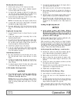
Mowing Tips
■ Look down and to the rear and make sure area is
clear before operating in reverse.
■ Do not operate or transport on steep slopes.
■ Do not stop, start, or change directions sudden-
ly on slopes.
■ Use extreme care and reduce ground speed on
slopes and rough terrain.
■ Watch for hidden hazards on the terrain during
operation.
■ Stop power unit and equipment immediately
upon striking an obstruction. Turn off engine,
remove key, inspect, and repair any damage be-
fore resuming operation.
Maximum recommended ground speed for cutting or
shredding is 6 miles per hour. Adjust tractor ground
speed by using higher or lower gears to provide a clean
cut without lugging tractor engine.
Tall material should be cut twice. Cut material higher
the first pass. Cut at desired height at 90 degrees the
second pass.
Remember, sharp blades produce cleaner cuts and
use less power.
Before entering an area, analyze it to determine the
best procedure. Consider the height and type of mate-
rial to be cut and the terrain type (hilly, level or rough,
etc.).
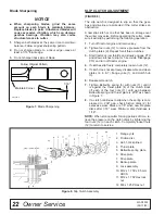
Shredding
The cutter may be used to shred various crops includ-
ing green manure, straw, stubble, asparagus residue,
corn stalks and similar crops in preparation for tilling. It
may also be used to shred pruning in orchards, groves
and vineyards.
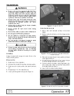
Each shredding operation may require a different set-
up. Start with front edge of cutter high. Adjust up or
down as necessary with attitude rod. Experiment until
you obtain the results you want.
When shredding attitude is set, check that the distance
from the bottom rear edge of the wing to the ground
matches the bottom edge of the rear center section to
the ground.
WARNING
CAUTION


