background image

Safety

 9

BW12_SR (2/6/2014)

(Safety Rules continued from previous page)

Full chain shielding must be installed at all

times.  Thrown objects could injure people or dam-
age property.

• If the machine is not equipped with full chain
shielding, operation must be stopped.
• This shielding is designed to reduce the risk
of thrown objects. The mower deck and protec-
tive devices cannot prevent all objects from
escaping the blade enclosure in every mowing
condition. It is possible for objects to ricochet
and escape, traveling as much as 300 feet
(92m).

Never direct discharge toward people, animals,

or property.

Do not operate or transport equipment while

under the influence of alcohol or drugs.

Operate only in daylight or good artificial light.

Keep hands, feet, hair, and clothing away from

equipment while engine is running. Stay clear of all
moving parts.

Always comply with all state and local lighting

and marking requirements.

Never allow riders on power unit or attachment.

Power unit must be equipped with ROPS or

ROPS cab and seat belt. Keep seat belt securely
fastened. Falling off power unit can result in death
from being run over or crushed. Keep foldable
ROPS system in “locked up” position at all times.

Always sit in power unit seat when operating

controls or starting engine. Securely fasten seat
belt, place transmission in neutral, engage brake,
and ensure all other controls are disengaged
before starting power unit engine.

Operate tractor PTO at 540 RPM. Do not exceed.

Raise or lower wings slowly to prevent personal

injury or damage to cutter.

Look down and to the rear and make sure area

is clear before operating in reverse.

Do not operate or transport on steep slopes.

Do not stop, start, or change directions sud-

denly on slopes.

Watch for hidden hazards on the terrain during

operation.

Stop power unit and equipment immediately

upon striking an obstruction. Turn off engine, set
parking brake, remove key, inspect, and repair any
damage before resuming operation.

Continuous operation while the clutch is slip-

ping could cause heat build-up resulting in fire.
Adjust slip clutch pressure by tightening springs to
the dimension shown in the “Owner Service” sec-
tion. If clutch is set to minimum spring length,
replace the friction disks as shown.

MAINTENANCE

Before cleaning, servicing, adjusting, repairing

or unplugging, stop tractor engine, place all con-
trols in neutral, set park brake, remove ignition key,
and wait for all moving parts to stop.

Before dismounting power unit or performing

any service or maintenance, follow these steps:
disengage power to equipment, lower the 3-point
hitch and all raised components to the ground,
operate valve levers to release any hydraulic pres-
sure, set parking brake, stop engine, remove key,
and unfasten seat belt.

Do not modify or alter or permit anyone else to

modify or alter the equipment or any of its compo-
nents in any way.

Your dealer can supply original equipment

hydraulic accessories and repair parts. Substitute
parts may not meet original equipment specifica-
tions and may be dangerous.

 To prevent contamination during maintenance

and storage, clean and then cover hose ends, fit-
tings, and hydraulic ports with tape.

Do not allow bystanders in the area when oper-

ating, attaching, removing, assembling, or servic-
ing equipment.

(Safety Rules continued on next page)

SAFETY RULES

ATTENTION! BECOME ALERT! YOUR SAFETY IS INVOLVED!

Summary of Contents for BATWING BW12

Page 1: ...OPERATOR S MANUAL BATWING ROTARY CUTTER MAN1078 Rev 4 1 2021 BW12...

Page 2: ...at www WoodsEquipment com or in the United States and Canada call 1 800 319 6637 The equipment you have purchased has been carefully engineered and manufactured to provide dependable and satisfactory...

Page 3: ...NING 23 TROUBLESHOOTING 24 DEALER SERVICE 25 DEALER SERVICE 25 GEARBOX MAINTENANCE 25 SEAL REPAIR 26 GEARBOX REPAIR 27 SPLITTER GEARBOX REPAIR 28 CROSSBER REMOVAL 30 CROSSBAR INSTALLATION 31 UNIVERSAL...

Page 4: ...carefully It fur nishes information and instructions that will help you achieve years of dependable performance These instructions have been compiled from extensive field experience and engineering da...

Page 5: ...free at TheAEMStore https youtu be uEWXsDqhDq0 It reinforces the proper procedures to follow while operating your mowing equipment The video does not replace the information contained in the Operator...

Page 6: ...wers Cutters English AEM Industrial Agricultural Mower Safety Manual English AEM Agricultural Tractor Safety Manual English Training Package for Rotary Mowers Cutters English Spanish Contains DVD VHS...

Page 7: ...draulic system by operating all hydraulic functions several times Do this before putting into service or allowing anyone to approach the equipment Make sure all hydraulic hoses fittings and valves are...

Page 8: ...ailures due to incorrect spline or incorrect operating length and can result in personal injury or death TRANSPORTATION Power unit must be equipped with Roll Over Protection System ROPS or ROPS cab an...

Page 9: ...re area is clear before operating in reverse Do not operate or transport on steep slopes Do not stop start or change directions sud denly on slopes Watch for hidden hazards on the terrain during opera...

Page 10: ...cals are installed Replace if damaged See Safety Decals section for location Make sure shields and guards are properly installed and in good condition Replace if damaged Never perform cleaning service...

Page 11: ...er edges of decals causing them to peel or come off Replacement safety decals can be ordered free from your Woods dealer To locate your nearest dealer check the Dealer Locator at www WoodsEquipment co...

Page 12: ...DES AND THROWN OBJECTS Do not put hands or feet under or into mower when engine is running Before mowing clear area of objects that may be thrown by blade Keep bystanders away Keep guards in place and...

Page 13: ...being raised or lowered FAILURE TO FOLLOW THESE INSTRUCTIONS COULD RESULT IN SERIOUS INJURY OR DEATH WARNING 1003751 A 13 PN 1003751 RAISED WING EXPOSES BLADE AND INCREASES THROWN OBJECT HAZARDS Only...

Page 14: ...ystanders in the area when oper ating attaching removing assembling or servic ing equipment Make sure spring activated locking pin or collar slides freely and is seated firmly in tractor PTO spline gr...

Page 15: ...e 4 Restart engine and straighten angle slightly shut off engine and try to connect CV driveline to tractor 5 Repeat the process until the driveline can be connected The point at which the driveline c...

Page 16: ...utch with replacement fiber disc The slip clutch is designed to slip when excessive torsional loads occur Move slowly into material Adjust tractor ground speed to provide a clean cut without lugging t...

Page 17: ...not operate or transport equipment while under the influence of alcohol or drugs Always comply with all state and local lighting and marking requirements Turn on flashing warn ing lights whenever tra...

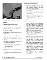
Page 18: ...ck all lubrication points and grease as instructed in lubrication information Make sure the PTO slip joint is lubricated and that the gear box fluid levels are correct ___ Set tractor PTO at correct r...

Page 19: ...or or filter mask where appropriate BLOCKING METHOD To minimize the potential hazards of working under neath the cutter follow these procedures Before performing any service or maintenance lower equip...

Page 20: ...until oil runs out the side plug on gearbox Check gearbox daily for evi dence of leakage and contact your dealer if leakage occurs Use sealant on vent plug threads during instal lation Check vent plu...

Page 21: ...ades Substitute blades may not meet original equipment specifications and may be dangerous Crossbar rotation has clockwise rotation on left gearbox and counterclockwise rotation on the right and cente...

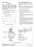
Page 22: ...operation 1 Turn off tractor engine and remove key 2 Remove driveline from tractor PTO 3 Loosen six 10 mm cap screws 6 to remove all tension from Belleville spring plate 5 4 Hold clutch hub 3 solid an...

Page 23: ...se long enough to allow you to stand to the side not in front of or over the tire assembly Use a safety cage if available Check wheels for low pressure cuts bubbles dam aged rims or missing lug bolts...

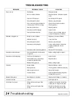
Page 24: ...te Set height so blades do not hit ground Excessive lush and tall vegetation Recut at 90 to first pass Excessive side skid wear Running with skids continuously on ground Raise cutting height or adjust...

Page 25: ...lacing gears shafts and a housing is not cost effective Pur chasing a complete gearbox is more economical 2 Inspect gearbox for leakage and bad bearings Leakage is a very serious problem and must be c...

Page 26: ...ut the side level plug 7 Remove and replace any seal damaged in installation Horizontal Seal Leak Repair 1 Disconnect and remove the rear driveline from the gearbox 2 Remove vent plug 9 and siphon gea...

Page 27: ...gear surfaces are rough when new Check that wear pattern is smooth 14 Inspect vertical and horizontal shafts for grooves nicks or bumps in the areas where the seals seat Resurface any damage with emer...

Page 28: ...sing a punch through the front opening of the gearbox and push shaft 1 and bearing 5 out the backside of housing 12 Remove gear 6 from inside housing 13 Remove bearing 7 and shim 8 by using a hammer a...

Page 29: ...gearbox for leaks by plugging all holes except one applying 4 psi of compressed air and immersing gearbox in water Verify gearbox does not leak NOTE Excessive air pressure will damage seals 3 Remove g...

Page 30: ...lic jack removal 6 For removal with puller screw attach tube 5 to each clevis with bolts 2 and nuts 3 Place pad 4 in nut and thread puller screw 6 into nut from bottom Tighten until pad is solid again...

Page 31: ...RSAL JOINT REPAIR Figure 16 U Joint Exploded View U Joint Disassembly 1 Remove external snap rings from yokes in four locations as shown in Figure 17 Figure 17 2 With snap rings removed support drive...

Page 32: ...okes in all directions to check for free movement If movement is restricted rap on yokes sharply with a hammer to relieve any tension Repeat until both yokes move in all directions without restriction...

Page 33: ...lic leak down hydraulic system failures or mechanical component failures Do not disconnect hydraulic lines until machine is securely blocked or placed in lowest position and system pressure is release...

Page 34: ...low to change unit over 1 Remove hose 6 attached to bulkhead fitting 5 under height cylinder 2 Remove the plug from side of cylinder 3 Install adapter 3 found in manual tube into cylinder 4 Remove tee...

Page 35: ...w to determine the turning lim its of the CV PTO driveline ___ Show customer the safe proper procedures to be used when mounting dismounting and storing equipment ___ Make customer aware of optional e...

Page 36: ...36 Dealer Check Lists MAN1078 2 6 2014 NOTES...

Page 37: ...39 MAIN ASSEMBLY 40 WING ASSEMBLY 42 TONGUE ASSEMBLY 43 HOSE ASSEMBLY 44 GEARBOX ASSEMBLY CAST CROWN TOP 45 SPLITTER GEARBOX ASSEMBLY 46 47 DRIVE ASSEMBLY CENTER DECK 48 WING 48 CV DRIVE 49 WHEEL TIR...

Page 38: ...38 Parts MAN1078 2 6 2014 CENTER FRAME ASSEMBLY Rev 3 17 2020...

Page 39: ...8345 3 Pin 1 00 x 4 08 29 16231 2 Bolt hex flange 5 16 NC x 50 GR5 30 19024 4 Bolt hex flange 5 8 NC x 1 75 GR5 31 19025 8 Nut hex flange 5 8 NC Dri Loc patch 32 24611 1 Sign SMV Slow Moving Vehicle 3...

Page 40: ...40 Parts MAN1078 2 6 2014 MAIN ASSEMBLY 27 Complete Decal Set 28 Safety Decal Set 29 Spanish Safety Decal Set Rev 1 9 2015...

Page 41: ...oke left 13 1038065RP 1 Transport lock up 14 1038084RP 1 Attitude rod 15 1038095 2 39 8 x 56 4 Drv asy cmpl W300E 16 1038100 9 1 0 x 3 84 Pin 17 1038881 2 2 x 10 cylinder 1 06 rod 17A 1038882 1 Seal k...

Page 42: ...lade kit 1003490 left wing 16 70065 12 1 4 NC Whiz nut 17 70046 12 25 20 x 75 Hex MR Whiz bolt 18 300105 1 5 16 NC x 2 HHCS GR5 ZP 19 1002048 1 Clutch shield 100 143 MM BC 20 1009199 2 2 04 Pin blade...

Page 43: ...x 1 x 9 16 Sleeve HT 8 1038072RP 1 CV drive holder 9 W8424 1 3 4ID 20D 3 8 Washer thick 10 13759 3 3 4 NC x 2 1 4 HHCS GR5 ZP 11 28873 2 3 4ID 1 1 20D 1 4 Washer thick 12 14069 1 1 2 NC x 3 1 4 HHCS 1...

Page 44: ...2 1 2 NPTM 9 16 JICM Adapter 4 1038891 2 1 4NPTF 1 2NPTM Adapter rstr 06 5 1009496 1 9 16 JIC 9 16 JIC Adapter 6 1038123 2 Hose 1 4 154 1 4NPT 9 16JICF 90 7 66511 2 1 2 NPT Male coupler 8 63480 2 3 8...

Page 45: ...plug and washer REF PART QTY DESCRIPTION 10 1018329 A R Output gasket 0 30 11 1018330 A R Output gasket 0 13 12 4 Lock washer 13 4 M10 x 1 5 x 25 Cap screw 14 1018331 1 1 14 Slotted flange nut 15 1 C...

Page 46: ...46 Parts MAN1078 2 6 2014 SPLITTER GEARBOX ASSEMBLY...

Page 47: ...earing 7 1005305 2 Gear 8 39414 2 Bearing 9 1005306 4 Shim 10 1 Casting 11 57320 2 Snap ring 12 57318 2 Oil seal 13 1005307 2 Shim 14 1034979 1 Bearing 15 1005303 1 Shaft 1 3 4 20 spline center 16 100...

Page 48: ...ip yoke 13 40780 1 Support bearing 14 40778 2 Screw package of 10 15 18864 1 Decal danger 16 33347 1 Decal danger REF PART PART QTY DESCRIPTION CENTER DECK DRIVE WING DRIVE 17 40779 1 Grease fitting 1...

Page 49: ...6 1024636 2 Drive shield bearing kit 7 18864 1 Decal danger rotating driveline see page 12 8 1038892 1 CV shield outer 9 1038894 1 CV shield inner 10 33347 1 Decal danger guard missing see page 13 11...

Page 50: ...1 1 Washer 10 1017032 1 Castle nut for use with Style A 11 1017035 1 Hub cap 12 1017038 5 Stud 13 1017069 1 Cotter pin 14 1017067 1 Grease fitting 15 35317 5 Nut lug 1 2 NF REF PART QTY DESCRIPTION 16...

Page 51: ...egment 4 1 1 Segment 5 1 3 4 Segment REF PART QTY DESCRIPTION A 8811 1 Crossbar puller complete 1 19914RP 2 Crossbar puller clevis 2 3097 4 5 8 NC x 4 1 2 HHCS GR5 3 230 4 5 8 NC Hex nut REF PART QTY...

Page 52: ...1 2 467 634 722 979 1020 1383 Diameter Thread Pitch Millimeters Wrench Size Coarse Thread Fine Thread Diameter Thread Pitch Millimeters Marking on Head Marking on Head Metric 8 8 Metric 10 9 Metric 8...

Page 53: ...etc HHCS Hex Head Cap Screw HT Heat Treated JIC Joint Industry Council 37 Flare LH Left Hand LT Left m Meter mm Millimeter M Male MPa Mega Pascal N Newton NC National Coarse NF National Fine NPSM Nat...

Page 54: ...Product Registration 2 Specifications 4 Table of Contents 3 Warranty Product 54 Replacement Parts 53 OPERATION Connecting Cutter to Tractor 14 Cutting Height Adjustment 15 CV Driveline Turning Limits...

Page 55: ...DS in its sole discretion deems it to be defective or in noncompliance with this Warranty The product must be returned to WOODS with proof of purchase within thirty 30 days after such defect or noncom...

Page 56: ...product must be returned to WOODS with proof of purchase within thirty 30 days after such defect or noncompliance is discovered or should have been discovered routed through the dealer and distributo...

Reviews: