Operation
17
MAN0725 (10/3/2008)
Use extreme care and reduce ground speed on
slopes and rough terrain.
Watch for hidden hazards on the terrain during
operation.
Stop power unit and equipment immediately
upon striking an obstruction. Turn off engine,
remove key, inspect, and repair any damage before
resuming operation.
Maximum recommended ground speed for cutting or
shredding is 6 miles per hour. Adjust tractor ground
speed by using higher or lower gears to provide a clean
cut without lugging tractor engine.
Tall material should be cut twice. Cut material higher
the first pass. Cut at desired height at 90 degrees the
second pass.
Remember, sharp blades produce cleaner cuts and
use less power.
Before entering an area, analyze it to determine the
best procedure. Consider the height and type of mate-
rial to be cut and the terrain type (hilly, level or rough,
etc.).
Shredding
The cutter may be used to shred various crops includ-
ing green manure, straw, stubble, asparagus residue,
corn stalks and similar crops in preparation for tilling. It
may also be used to shred pruning in orchards, groves
and vineyards.
Each shredding operation may require a different set-
up. Start with front edge of cutter high. Adjust up or
down as necessary with attitude rod. Experiment until
you obtain the results you want.
When shredding attitude is set, check that the distance
from the bottom rear edge of the wing to the ground
matches the bottom edge of the rear center section to
the ground. With the cutting height and attitude estab-
lished, adjust the driveline carrier bearing in the H-
frame to ensure the front driveline is parallel to the
ground.
TRANSPORTING
Always raise unit and install transport locks
before transporting. Leak down or failure of
mechanical or hydraulic system can cause equip-
ment to drop.
Always attach safety chain to tractor drawbar
when transporting unit.
Never exceed 20 mph (32.2 km/h) during trans-
port.
Never allow riders on power unit or attachment.
Do not operate PTO during transport.
Do not operate or transport on steep slopes.
Do not operate or transport equipment while
under the influence of alcohol or drugs.
Always comply with all state and local lighting
and marking requirements.
Lock-Up
Always transport with wings and center frame in the
raised, locked position.
Wing Lock-Up
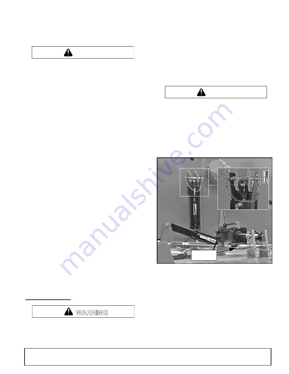
Figure 2
. Transport Lock-Up
Wing and Center Section Shown
1.
Remove safety pin and lock-up pin from storage
position.
2.
Raise wing and align wing transport lock with
slotted holes in the cylinder lugs.
3.
Insert lock-up pin above cylinder pin and secure
with klik pin
4.
Repeat steps 1 to 3 for opposite wing.
5.
Relieve hydraulic pressure from wing cylinders and
lower wing against wing transport lock.
CAUTION
WARNING
CAUTION
DP2
Pin Storage
Position
(Rev. 1/9/2009)
Summary of Contents for Batwing BW240Q
Page 1: ...OPERATOR S MANUAL BATWING MAN0725 Rev 9 11 2013 BW240 BW240Q...
Page 46: ...46 Parts MAN0725 10 3 2008 MAIN FRAME ASSEMBLY FRONT SECTION Rev 9 11 2013...
Page 48: ...48 Parts MAN0725 10 3 2008 MAIN FRAME ASSEMBLY REAR SECTION...
Page 50: ...50 Parts MAN0725 10 3 2008 WING ASSEMBLY Rev 9 21 2009 Right Wing Shown...
Page 52: ...52 Parts MAN0725 10 3 2008 WING CENTER GEARBOX ASSEMBLY...


