Assembly
39
MAN0632 (5/15/2007)
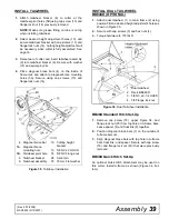
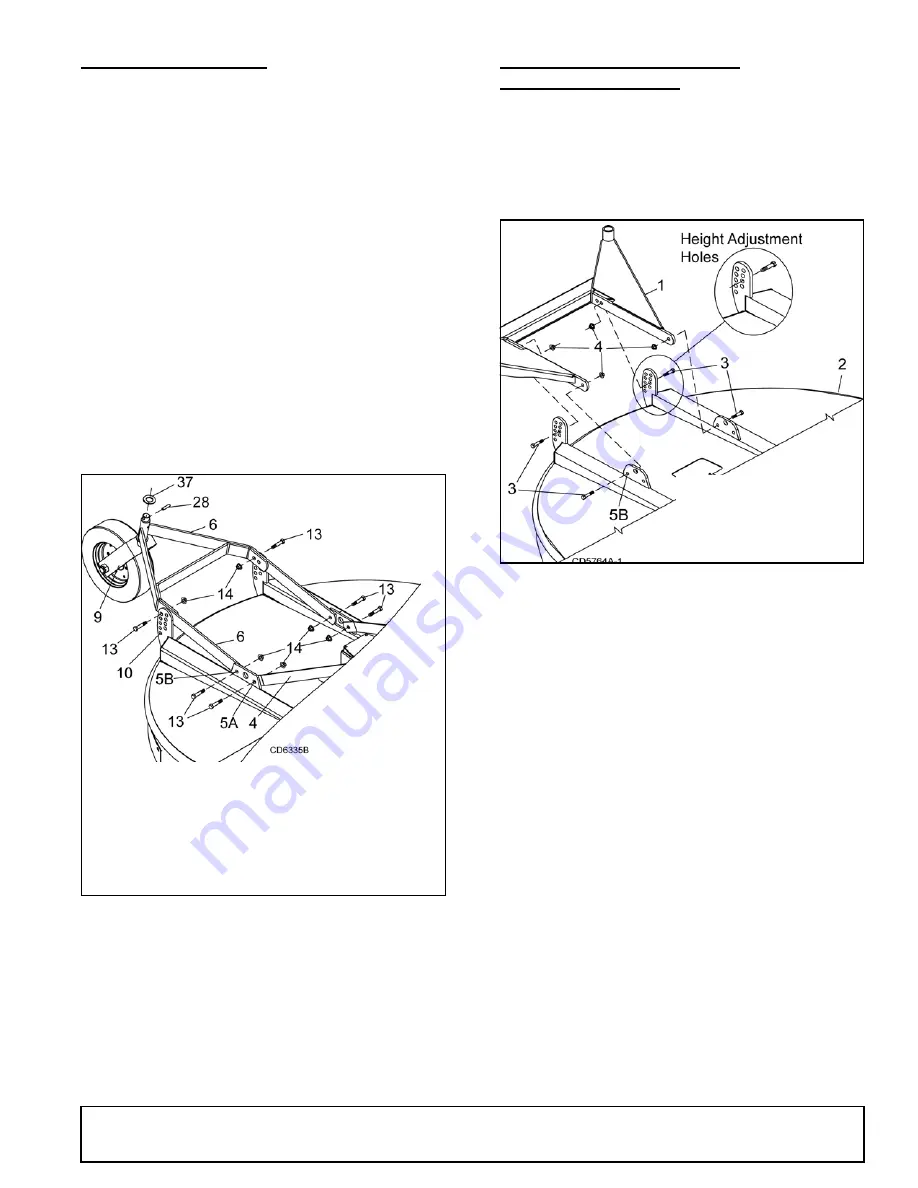
INSTALL TAILWHEEL
1.
Attach tailwheel bracket (6) to cutter at the
tailwheel pivot holes (5B) using cap screw (13) and
flange lock nut (14) previously removed.
NOTE:
Make sure grease fitting on tube is on top
when installing tailwheel.
2.
Select desired height adjustment holes (10), and
secure tailwheel bracket with cap screws (13) and
flange lock nuts (14). Cutting height adjustment will
be necessary when cutter is fully assembled. See
page 16.
3.
Raise rear of cutter and insert tailwheel assembly
(9) into tailwheel bracket (6). Secure with washer
(37) and spiral pin (28).
4.
Place diagonal brace bars (4) on the inside of
frame rails and attach to diagonal brace mounting
holes (5A). Secure using cap screws (13) and
flange lock nuts (14).
Figure 35
. Tailwheel Installation
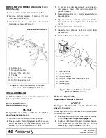
INSTALL DUAL TAILWHEEL
BB84XD (OPTIONAL)
1.
Attach dual tailwheel (1) to main frame (2) using
position 5B and desired height adjustment holes as
shown in Figure 36.
2.
Secure with cap screws (3) and hex nuts (4).
3.
Torque hardware to 175 lbs-ft.
Figure 36
. Dual Tailwheel Installation
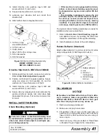
BB48X Standard Hitch Set-Up
1.
Remove cap screw (18), upper Figure 34, and
flange lock nut (20) from top hole on A-frame bars.
Leave spacer (8) and float link (9) together.
2.
Position diagonal brace bars (7) on the outside of
A-frame bars (6).
3.
Align diagonal brace bars with top hole in A-frame
bars, float link, and spacer. Secure with cap screw
(18) and flange lock nut (20) that were previously
removed.
BB48X Quick Hitch Set-Up
An optional Quick Hitch attachment may be used on
this cutter. Install A-frame as shown (Figure 34, bot
-
tom).
4. Diagonal brace bar
5A. Diagonal brace
mounting hole
5B. Tailwheel pivot hole
6. Tailwheel bracket
9. Tailwheel assembly
10. Cutting height
bracket
13. 5/8 NC x 2 HHCS
14. 5/8 NC Flange nut
28. Spirol pin
37. 33 mm Flat washer
1. Dual tailwheel
2. Deck, BB84XD
3. 5/8 NC x 2-1/2 HHCS
4. 5/8 Flange lock nut
(Rev. 5/10/2009)

