background image

F-3079 (Rev. 7/31/2017)

WOODS

®| 

A Blount International Brand

2606 South Illinois Route 2 
Post Office Box 1000
Oregon, Illinois 61061 USA

800-319-6637 tel
800-399-6637 fax
woodsequipment.com

WARRANTY

All Models Except Mow’n Machine

TM

 Zero-Turn Mowers

Please Enter Information Below and Save for Future Reference.

Date Purchased:  ____________________________

From (Dealer): __________________________________________

Model Number:  ____________________________

Serial Number: __________________________________________

Woods Equipment Company (“WOODS”) warrants this product to be free from defect in material and workmanship. Except as otherwise set forth
below, the duration of this Warranty shall be for TWELVE (12) MONTHS COMMENCING ON THE DATE OF DELIVERY OF THE
PRODUCT TO THE ORIGINAL PURCHASER. 

All current model backhoes, loaders and mounts (except 3-pt. SAF-T-LOK

 mounts) are warranted for two (2) years from the date of delivery to

the original purchaser.  The limited warranty covers any defects in the material and/or workmanship.  Following the proper, recommended
installation by an authorized Woods Dealer and normal use of a Woods mounting and backhoe or loader, if a tractor incurs damage resulting from
the attachment, Woods will cover the existing tractor warranty in the event the manufacturer voids its tractor warranty because of the attachment.
Warranty does not cover any misuse or abusive conditions that could cause premature wear or damage to attachment or tractor. 

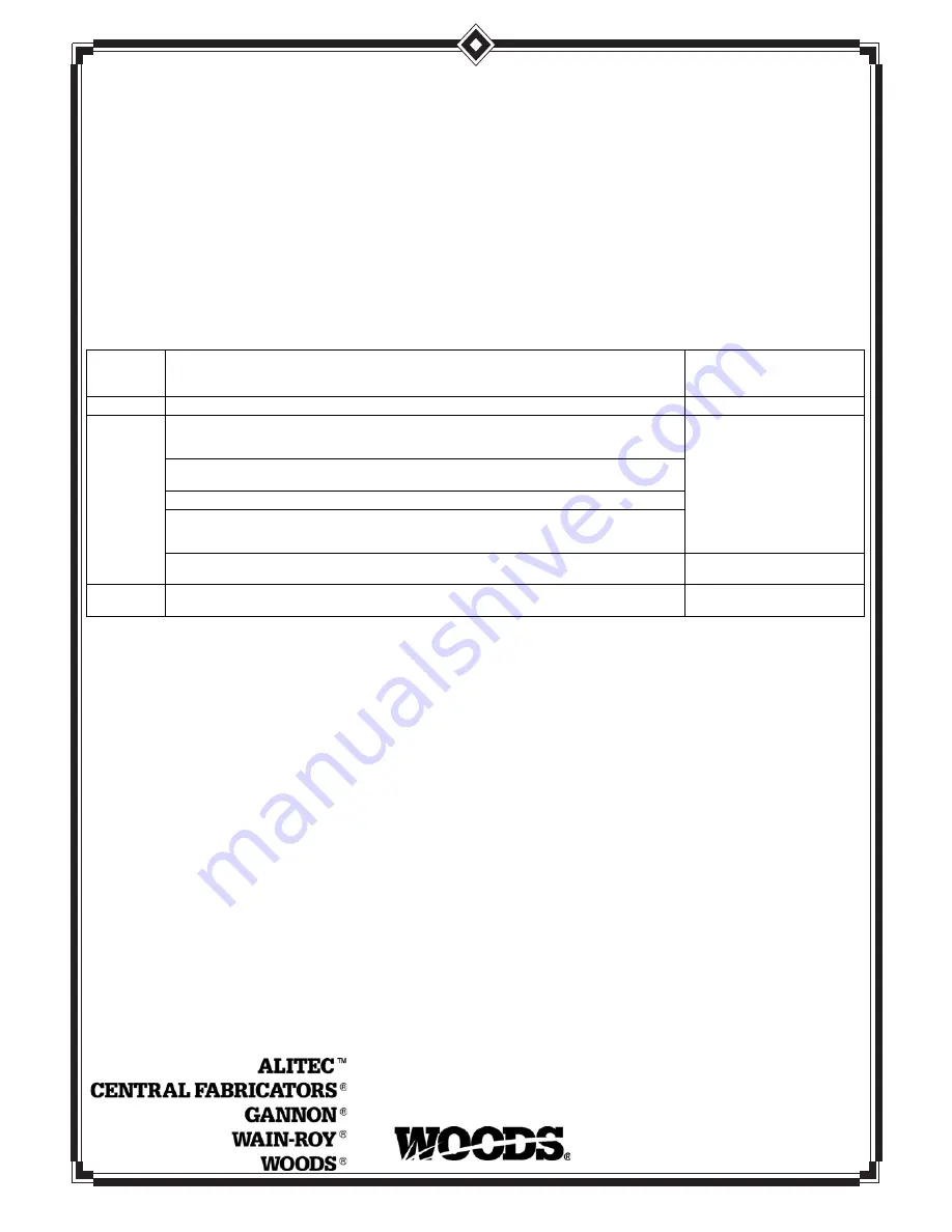
The warranty periods for specific parts or conditions are listed below:

Under no circumstances will this Warranty apply in the event that the product, in the good faith opinion of WOODS, has been subjected to
improper operation, improper maintenance, misuse, or an accident. This Warranty does not apply in the event that the product has been materially
modified or repaired by someone other than WOODS, a WOODS authorized dealer or distributor, and/or a WOODS authorized service center.
This Warranty does not cover normal wear or tear, or normal maintenance items. This Warranty also does not cover repairs made with parts other
than those obtainable through WOODS.

This Warranty is extended solely to the original purchaser of the product. Should the original purchaser sell or otherwise transfer this product to a
third party, this Warranty does not transfer to the third party purchaser in any way. There are no third party beneficiaries of this Warranty.

WOODS makes no warranty, express or implied, with respect to engines, batteries, tires or other parts or accessories not manufactured by
WOODS. Warranties for these items, if any, are provided separately by their respective manufacturers.

WOODS’ obligation under this Warranty is limited to, at WOODS’ option, the repair or replacement, free of charge, of the product if WOODS, in
its sole discretion, deems it to be defective or in noncompliance with this Warranty. 

The product must be returned to WOODS with proof of

purchase within thirty (30) days after such defect or noncompliance is discovered or should have been discovered, routed through the
dealer and distributor from whom the purchase was made, transportation charges prepaid.

 WOODS shall complete such repair or

replacement within a reasonable time after WOODS receives the product. THERE ARE NO OTHER REMEDIES UNDER THIS WARRANTY.
THE REMEDY OF REPAIR OR REPLACEMENT IS THE SOLE AND EXCLUSIVE REMEDY UNDER THIS WARRANTY.

THERE ARE NO WARRANTIES WHICH EXTEND BEYOND THE DESCRIPTION ON THE FACE OF THIS WARRANTY. WOODS
MAKES NO OTHER WARRANTY, EXPRESS OR IMPLIED, AND WOODS SPECIFICALLY DISCLAIMS ANY IMPLIED WARRANTY
OF MERCHANTABILITY AND/OR ANY IMPLIED WARRANTY OF FITNESS FOR A PARTICULAR PURPOSE.

WOODS shall not be liable for any incidental or consequential losses, damages or expenses, arising directly or indirectly from the
product, whether such claim is based upon breach of contract, breach of warranty, negligence, strict liability in tort or any other legal
theory. 

Without limiting the generality of the foregoing, Woods specifically disclaims any damages relating to (i) lost profits, business, revenues

or goodwill; (ii) loss of crops; (iii) loss because of delay in harvesting; (iv) any expense or loss incurred for labor, supplies, substitute machinery or
rental; or (v) any other type of damage to property or economic loss.

This Warranty is subject to any existing conditions of supply which may directly affect WOODS’ ability to obtain materials or manufacture
replacement parts.

No agent, representative, dealer, distributor, serviceperson, salesperson, or employee of any company, including without limitation, WOODS, its
authorized dealers, distributors, and service centers, is authorized to alter, modify, or

Part or 

Condition 

Warranted

Model Number

Duration (from date of 
delivery to the original 

purchaser)


All units invoiced after 4/30/2012

Gearbox 

components

BB48X, BB60X, BB72X, BB84X, BB600X, BB720X, BB840X, BB6000X, BB7200X, BB8400X,
DS12.50, TS14.60, DS1440, TS1680, DS8.30, DS10.40, DS8.50, DSO8.50, DS10.50, DSO10.50,
DBH5.30, DBH6.30

6 years

BW12, BW15, BW126X, BW180X, BW126XHD, BW180XHD, BW1260X, BW1800X
BW10.50, BW10.50Q, BW15.50, BW15.50Q, BW15.60, BW15.60Q, BW10.60, BW10.60Q

BW240X, BW240XHD, BW1620X, BW2400X

RD990X, PRD6000, PRD7200, PRD8400,  S15CD, S20CD, S22CD, S25CD, S27CD, S30CD, TC/
R74, TC/R68, TC/R60, TBW144, TBW180, TBW204, TSG50, S12ED, S15ED, S18ED, S20ED,
TPD25, TPD35, TPD65, TPD95

RDC54, RD60, RD72, TBW150C, TS/R60, TS/R52, TS/R44, RC3.5, RC4, RC5, RC6

3 years (1 year if used in rental or 
commercial applications)

Blade 

spindles

RD990X, PRD6000, PRD7200, PRD8400, TBW144, TBW180, TBW204

3 years 

Summary of Contents for BRUSHBULL BB48X

Page 1: ...OPERATOR S MANUAL BRUSHBULL ROTARY CUTTER MAN0632 Rev 5 21 2018 BB48X BB60X BB72X BB84X TM Serial Number 1159929 After Includes Service and Parts Information for Serial Number 1159928 Prior...

Page 2: ...at www WoodsEquipment com or in the United States and Canada call 1 800 319 6637 The equipment you have purchased has been carefully engineered and manufactured to provide dependable and satisfactory...

Page 3: ...R FORM 5 SAFETY RULES 7 SAFETY DECALS 10 OPERATION 12 OWNER SERVICE 18 TROUBLE SHOOTING 23 DEALER SERVICE 24 DEALER CHECK LISTS 34 ASSEMBLY INSTRUCTIONS 36 INDEX TO PARTS LISTS 43 BOLT TORQUE CHART 61...

Page 4: ...data Some information may be general in nature due to unknown and varying operating conditions However through experience and these instructions you should be able to develop procedures suitable to yo...

Page 5: ...free at TheAEMStore https youtu be uEWXsDqhDq0 It reinforces the proper procedures to follow while operating your mowing equipment The video does not replace the information contained in the Operator...

Page 6: ...wers Cutters English AEM Industrial Agricultural Mower Safety Manual English AEM Agricultural Tractor Safety Manual English Training Package for Rotary Mowers Cutters English Spanish Contains DVD VHS...

Page 7: ...guards do not rotate freely on drive lines repair and replace bearings before putting equipment into service Power unit must be equipped with ROPS or ROPS cab and seat belt Keep seat belt securely fas...

Page 8: ...e remove key inspect and repair any damage before resuming operation Leak down or failure of mechanical or hydraulic system can cause equipment to drop Before performing any service or maintenance dis...

Page 9: ...ge area Disconnect cutter driveshaft and secure up off ground Raise cutter with 3 point hitch Place blocks under cutter side skids Lower cutter onto blocks Disconnect cutter from tractor 3 point hitch...

Page 10: ...ACT OR THROWN OBJECTS CAN CAUSE SERIOUS INJURY OR DEATH DANGER ROTATING DRIVELINE CONTACT CAN CAUSE DEATH KEEP AWAY DO NOT OPERATE WITHOUT All driveline guards tractor and equipment shields in place D...

Page 11: ...OVER Tractor must be equipped with ROPS or ROPS CAB and seat belt Keep foldable ROPS systems in locked up position at all times Buckle Up Keep seat belt securely fastened Allow no riders RAISED EQUIP...

Page 12: ...mage before resuming operation Always wear relatively tight and belted clothing to avoid getting caught in moving parts Wear sturdy rough soled work shoes and protective equipment for eyes hair hands...

Page 13: ...s 6 floating link 3 cap screw 11 spacer 7 and flange lock nut 9 from upper hole on A frame bars 5 as shown on left in Figure 3 NOTE A Frame bars are installed to mast plates with carriage bolts throug...

Page 14: ...e placed in the lower holes of the A frame Quick Hitch 1 Position tractor 3 point arms between the mast plates and secure with hitch pins and cotter pin See right side of Figure 4 Note pin orientation...

Page 15: ...driveline is too short please call your Woods dealer for a longer driveline If driveline is too long please follow the instructions for shortening the driveline SHORTENING DRIVELINE 1 Move cutter up...

Page 16: ...er from side to side Check by measuring from cutter frame to the ground at each deck rail 2 Adjust using tractor 3 point arm leveling device NOTE Keep the front of cutter slightly lower than rear for...

Page 17: ...me grass and prevent cutting at the same height as the surrounding area When this occurs reduce your ground speed but maintain PTO at 540 rpm The lower ground speed will permit grass to rebound partia...

Page 18: ...verall stability of the blocked unit Just placing jackstands underneath will not ensure your safety The working surface must be level and solid to support the weight on the jackstands Make sure jackst...

Page 19: ...ply genuine replacement blades Substitute blades may not meet original equipment specifications and may be dangerous Crossbar rotation is counterclockwise when looking down on cutter Be sure to instal...

Page 20: ...lutch 1 Turn off tractor engine and remove key 2 Loosen nuts on springs until the springs can rotate freely yet remain secure on the bolts 3 Mark outer plates of slip disc clutch as shown in Figure 15...

Page 21: ...riction disc 3 Hub 1 3 8 round bore 4 Thrust plate 5 Belleville spring plate 6 10 mm x 1 5P x 55 mm Cap screw 7 10 mm x 1 5P Hex nut Compression Spring Style Clutch Belleville Spring Style Clutch Mode...

Page 22: ...broken Rubber Shielding Inspect rubber shielding each day of operation and replace if cracked or broken Optional Chain Shielding Inspect chain shielding each day of operation and replace any broken o...

Page 23: ...aterial along swath Material too high and too much material Reduce ground speed but maintain 540 RPM at tractor PTO or make two passes over material Raise cutter for the first pass and lower to desire...

Page 24: ...gears shafts and a housing is not cost effective Pur chasing a complete gearbox is more economical 2 Inspect gearbox for leakage and bad bearings Leakage is a very serious problem and must be correcte...

Page 25: ...housing through this opening 3 Remove cotter pin washer and nut from vertical shaft and remove crossbar see Crossbar Removal page 31 4 Remove the four bolts that attach gearbox to cutter and remove g...

Page 26: ...eth are a match 11 While holding gear 1 in place slide input shaft 3 through gear 1 and bearing 8 Align splines on shaft 3 and gear 1 12 Slide spacer 14 over input shaft 3 and press bearing onto input...

Page 27: ...B84X 21 Metric seal 40 x 80 x 12 22 Oil seal 23 Oil cup 25 Top cover 26 Cap screw 8 mm x 16 8 8 27 Vent plug 28 Cotter pin 1 Crown gear 2 Gearbox housing 3 Input shaft 4 Output shaft 5 Gear pinion 6 B...

Page 28: ...be until it runs out the side level plug 7 Remove and replace any seal damaged in installation Horizontal Seal Leak Repair 1 Disconnect and remove the rear driveline from the gearbox 2 Remove vent plu...

Page 29: ...output shaft and pinion 19 NOTE On gearboxes with tapered roller bearings it will be necessary to use a punch to drive out bearing cups 13 Inspect gears for broken teeth and wear Some wear is normal a...

Page 30: ...ing cone 25 over output shaft until seats against upper bearing 25 Press lower bearing cup into position as shown 7 Secure output cap 17 with new output seal 16 installed to bottom of gearbox housing...

Page 31: ...ydraulic jack removal 6 For removal with puller screw attach tube 5 to each clevis with bolts 2 and nuts 3 Place pad 4 in nut and thread puller screw 6 into nut from bottom Tighten until pad is solid...

Page 32: ...BB60X BB72X 200 lbs ft BB84X 300 lbs ft 3 Install the blades using existing hardware Torque blade pin nut to 85 lbs ft Figure 23 UNIVERSAL JOINT REPAIR Figure 24 Universal Joint Parts Breakdown U Joi...

Page 33: ...Be careful not to disturb needle bearings Insert another bearing cup directly across from first cup and press in as far as possible with hand pressure 2 Trap cups in vise and apply pressure Be sure jo...

Page 34: ...TY ___ Show customer how to make adjustments Describe the options available for this cutter and explain their purpose ___ Explain importance of lubrication to customer and point out lubrication points...

Page 35: ...Dealer Check Lists 35 MAN0632 5 15 2007 NOTES...

Page 36: ...e comes within 300 feet 92 m This shielding is designed to reduce the risk of thrown objects The mower deck and protec tive devices cannot prevent all objects from escaping the blade enclosure in ever...

Page 37: ...at are securing tailwheel bracket 6 and diagonal brace bars 4 to cutter Figure 32 Shipping Unit Disassembly BB48X Shown 2 A Frame bar 3 Upper mounting hardware 4 Diagonal brace 5A Diagonal brace bar m...

Page 38: ...on to diagonal brace bars INSTALL A FRAME TO DIAGONAL BRACE BARS Figure 34 Diagonal Brace Bars to A Frame Connection BB48X Only 6 A Frame bar 9 Top link assembly 12 5 8 NC Flange lock nut 19 5 8 x 1 x...

Page 39: ...l 1 to main frame 2 using position 5B and desired height adjustment holes as shown in Figure 36 2 Secure with cap screws 3 and hex nuts 4 3 Torque hardware to 175 lbs ft Figure 36 Dual Tailwheel Insta...

Page 40: ...g ring 6 in slot on input shaft and snap into place 5 Align the holes in the driveline yoke and gearbox input shaft Install and tighten shear bolt 4 and nut 3 6 Install rear drive shield to driveline...

Page 41: ...of thrown objects The mower deck and protec tive devices cannot prevent all objects from escaping the blade enclosure in every mowing condition It is possible for objects to ricochet and escape travel...

Page 42: ...to each side of tractor top link bracket 10 with bolt 4 and nut 5 4 Insert check chains through keyhole brackets and set cutter height Figure 41 Check Chain Installation BB60X BB72X BB84X 1 Check cha...

Page 43: ...ER STANDARD DRIVELINE 52 BB48X BB60X SLIP CLUTCH DRIVELINE ASSEMBLY OPTIONAL 53 BB48X BB60X COMER SLIP CLUTCH DRIVELINE OPTIONAL 54 BB72X SLIP CLUTCH DRIVELINE ASSEMBLY 55 BB72X COMER SLIP CLUTCH DRIV...

Page 44: ...mbly BB84XD optional 6 1021569 2 A Frame bar BB48X 6 1023059 2 A Frame bar BB60X 6 1021556 2 A Frame bar BB72X 6 1024123 2 A Frame bar BB84X REF PART QTY DESCRIPTION 7 57239 2 Diagonal brace BB48X 7 1...

Page 45: ...7 24409 2 5 16 NC x 1 Carriage bolt 38 4529 2 5 16 NC Hex nut 39 7163 1 Washer 1 1 4 STD Flat 40 2 Cotter Pin 41 300300 4 1 2 NC x 1 HHCS GR5 42 4 1 2 Flat washer 43 4676 1 4 x 15 Notat tire rim 44 15...

Page 46: ...ng 3 57464 1 Input shaft 1 3 8 smooth shaft BB48X BB60X 3 57465 1 Input shaft 1 3 8 6 spline BB72X 3 57147 1 Input shaft 1 3 8 6 spline BB84X 4 57489 1 Output shaft BB48X BB60X 4 57490 1 Output shaft...

Page 47: ...3 x 1 BB84X 20 57473 1 Flat washer 21 x 37 x 3 BB48X BB60X 20 57474 1 Flat washer 25 x 48 x 2 5 BB72X 21 20900 1 Seal metric 40 x 80 x 12 BB48X BB60X BB72X 21 39289 1 Seal 50 x 90 x 10 BB84X 22 57463...

Page 48: ...6 1 Retaining ring 7 1 Gear spacer 8 1 Retaining ring 9 1011780 1 Vent plug and washer 10 1018329 A R Output gasket 0 30 11 1018330 A R Output gasket 0 13 12 4 Lock washer 13 4 M10 x 1 5 x 25 cap scr...

Page 49: ...Complete driveline asy 1 1044051 1 Complete collar yoke C12 1 3 8 6 2 1044050 1 Lock collar repair kit 3 1044052 2 Cross bearing kit 4 605246 1 Outer yoke tube 5 605248 1 Inner yoke tube 6 605250 1 O...

Page 50: ...ng kit 3 1019442 1 Outer cone fix ring 4 30922 6 Protection fixing screw 5 1019444 1 Inner cone fix ring 6 30917 2 Chain shield tether 9 1001340 1 Lock collar repair kit 10 1019445 1 Special drive yok...

Page 51: ...Complete driveline asy 1 1044051 1 Complete collar yoke C12 1 3 8 6 2 1044050 1 Lock collar repair kit 3 1044052 2 Cross bearing kit 4 605252 1 Outer yoke tube 5 605253 1 Inner yoke tube 6 605254 1 O...

Page 52: ...ix ring 4 30922 6 Protection fixing screw 5 1019444 1 Inner cone fix ring 6 30917 2 Chain shielding tether 9 1001340 1 Lock collar repair kit 10 1019445 1 Special drive yoke 11 1001302 1 Flexible pin...

Page 53: ...Cross bearing kit 4 605269 1 Outer yoke tube 5 605270 1 Inner yoke tube 6 605271 1 Outer shield with bearing 7 605272 1 Inner shield with bearing 9 1044077 1 Flanged yoke 10 1043994 1 Bushing 11 1044...

Page 54: ...Lock collar repair kit 10 1019446 1 Special friction clutch 11 1001311 8 Spring 12 1019447 1 Flanged yoke 13 1001313 1 Bushing 14 1001314 2 Lining ring 15 1019448 1 Special hub F10 16 1001317 1 Pressu...

Page 55: ...05252 1 Outer yoke tube 5 605253 1 Inner yoke tube 6 605254 1 Outer shield with bearing 7 605256 1 Inner shield with bearing 9 1044077 1 Flanged yoke 10 1043994 1 Bushing 11 1044083 2 Friction disc 12...

Page 56: ...9449 1 Friction clutch 11 1001311 8 Spring 12 1001312 1 Flanged yoke 13 1001313 1 Bushing 14 1001314 2 Lining ring REF PART QTY DESCRIPTION 15 1001316 1 Flanged hub F12 16 1001317 1 Pressure plate 17...

Page 57: ...er yoke tube 6 605281 1 Friction clutch assembly 7 605279 1 Outer shield with bearing 8 605280 1 Inner shield with bearing 9 605285 1 Pressure plate 10 605284 1 Internal disc 11 605286 2 Friction disc...

Page 58: ...lutch 11 1001311 1001311 8 Spring 12 1029690 1028779 1 Flange yoke 13 1028780 1028780 1 Bushing 14 1028781 1028781 1 Lining ring REF PART 60 Series PART 50 Series QTY DESCRIPTION 15 1029691 1028782 1...

Page 59: ...9 13 17 40777 2 Anti rotation chain 19 40589 1 Slide collar kit 20 40590 1 Outer guard half 21 40591 1 Inner guard half REF PART QTY DESCRIPTION 22 57410 1 Shaft assembly male complete with guard 23 N...

Page 60: ...Link 25 x 1 00 x 16 00 BB84X 3 6697 8 3 8 NC x 1 Carriage bolt 4 14350 8 3 8 NC Flange hex nut Standard hardware obtain locally REF QTY PART BB48X PART BB60X PART BB72X PART BB84X DESCRIPTION 1 1 5724...

Page 61: ...1 2 467 634 722 979 1020 1383 Diameter Thread Pitch Millimeters Wrench Size Coarse Thread Fine Thread Diameter Thread Pitch Millimeters Marking on Head Marking on Head Metric 8 8 Metric 10 9 Metric 8...

Page 62: ...etc HHCS Hex Head Cap Screw HT Heat Treated JIC Joint Industry Council 37 Flare LH Left Hand LT Left m Meter mm Millimeter M Male MPa Mega Pascal N Newton NC National Coarse NF National Fine NPSM Nat...

Page 63: ...utting Height 16 Shredding 16 Attaching Cutter to Tractor BB48X Attachment 12 Quick Hitch 13 Top Link Adjustment 13 BB60X BB72X BB84X Quick Hitch 14 Standard Hitch 14 Driveline Attachment 15 Interfere...

Page 64: ...DS obligation under this Warranty is limited to at WOODS option the repair or replacement free of charge of the product if WOODS in its sole discretion deems it to be defective or in noncompliance wit...

Page 65: ...nce with this Warranty The product must be returned to WOODS with proof of purchase within thirty 30 days after such defect or noncompliance is discovered or should have been discovered routed through...

Page 66: ...ames or service marks not owned by Woods Equipment Company that appear in this manual are the property of their respec tive companies or mark holders Specifications subject to change without notice WO...

Reviews: