Operation
9
MAN1255 (3/19/2018)
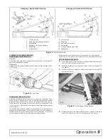
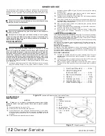
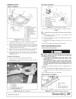
Figure 3
.
Quick Hitch Set-Up
CONNECTING AND REMOVING
DRIVELINE (TRACTOR PTO)
To Install:
Pull locking collar back and at the same time push driveline onto tractor PTO
shaft until locking device engages.
To Remove:
Hold driveline into position, pull locking collar back, and slide driveline off trac
-
tor PTO shaft.
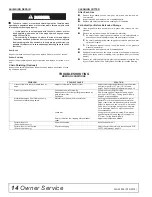
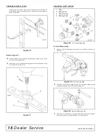
Figure 4
.
Lock Collar
DRIVELINE INSTALLATION
Attach the cutter to the tractor 3-point hitch (or quick hitch if available). Do not
attach driveline. Raise and lower cutter to determine maximum and minimum
distance between the tractor PTO shaft and the gearbox input shaft. If the dis
-
tance is too large, the driveline will be too short for proper engagement. If dis
-
tance is too small, the driveline may bottom out in operation and damage the
cutter or tractor.
The driveline length must be sufficient to provide at least 1/3 driveline length of
engagement during operation. There must be at least 101.6 mm (4 inches) of
engagement at the cutter’s lowest possible point of operation. The driveline
must not bottom out when raised to the maximum height possible.
If driveline is too short, please call your Woods dealer for a longer driveline.
If driveline is too long, please follow the instructions for shortening the driveline.
SHORTENING DRIVELINE
1.
Move cutter up and down to get the shortest possible distance between
tractor PTO shaft and gearbox input shaft.
2.
Separate driveline into two halves and connect them to the tractor PTO
and gearbox.
3.
Place driveline halves parallel to one another to determine how much to
shorten the driveline.
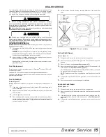
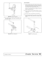
Figure 5
.
Drive Halves Placed Parallel
4.
Measure from end of the upper shield to the base of the bell on the lower
shield (A). Add 34.69 mm (1-9/16") to dimension (A). See Figure 6.
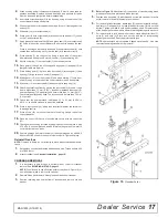
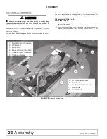
Category I Quick Hitch Set-Up
Category II Quick Hitch Set-Up
1. Tractor top link
2. Cutter top link attachment point
3. Floating link
5. Category I & II cutter hitch pin
6. Brace arm
7. A-frame arm
8. Quick-Hitch
9. Rear lug
10. Brace arm pivot hole
12. Break link
13. Second hole on pivot hole
15. Mast plate
DP2
Summary of Contents for BRUSHBULL BB600XE
Page 1: ...OPERATOR S MANUAL BRUSHBULL ROTARY CUTTER 3 19 2018 BB600XE BB720XE BB840XE MAN1255 TM...
Page 7: ...Declaration of Conformity 7 MAN1253 3 15 2018...
Page 24: ...24 Assembly MAN1255 3 19 2018 NOTES...
Page 28: ...28 Parts MAN1255 3 19 2018 GEARBOX ASSEMBLY...
Page 38: ...MANUEL D UTILISATION BRUSHBULL MAN1255 3 19 2018 BB600XE BB720XE BB840XE TM FAUCHEUSE ROTATIVE...
Page 44: ...7 D claration de Conformit MAN1255 3 19 2018 Declaration of Conformity...
Page 63: ...TRINCIATRICE ROTANTE BRUSHBULL 19 03 2018 MAN1255 TM BB600XE BB720XE BB840XE...
Page 69: ...Dichiarazione di conformit 7 MAN1253 15 03 2018...
Page 81: ...Assemblaggio 19 MAN1255 19 03 2018 NOTE...
Page 87: ...BRUSHBULL SICHELM HER 19 03 2018 BB600XE BB720XE BB840XE MAN1255 TM...
Page 93: ...Konformit tserkl rung 7 MAN1253 15 03 2018...
Page 105: ...Montage 19 MAN1255 19 03 2018 HINWEISE...
Page 111: ...BRUSHBULL DESBROZADORA GIRATORIA 19 3 2018 BB600XE BB720XE BB840XE MAN1255 TM...
Page 117: ...Declaraci n de conformidad 7 MAN1253 15 3 2018...
Page 129: ...Montaje 19 MAN1255 19 3 2018 NOTAS...


