Dealer Service
23
MAN0646 (Rev. 11/5/2007)
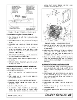
Figure 12
. Power Tilt Deck Safety Switch Layout
Troubleshooting Deck Safety Switch
1.
Pull handlebars in with deck in lowest cutting
height position (1).
2.
Check that switch is making contact with the height
gauge.
3.
Check that wires are properly hooked up to power
unit.
4.
Adjust switch bracket location on actuator if
needed (four screws). Make sure height screw
does not bottom out on slot in either direction when
raising or lowering deck.
5.
Check that screws holding switch to bracket are
not too tight and holding lever open.
6.
Adjust safety switch lever or replace switch if
necessary,
7.
After adjustments, check that engine cuts out with
deck partially raised.
HYDROSTATIC PUMP & BELT REMOVAL
NOTE:
Removal procedures are the same for both
right and left hydrostatic pumps.
1.
Place power unit on a level surface and remove
key.
2.
Place power unit on stands to allow access to
bottom of the machine.
3.
Drain hydraulic reservoir and hydrostatic pumps.
4.
Remove steering linkage from control arm on
hydrostatic pump.
5.
Loosen J-bolt and remove belt.
6.
If clearance between radiator cowl and engine
sheave is too tight, loosen or remove rubber
isolator (84) radiator mount located above the
engine. Push radiator forward until belt clears
radiator cowl and engine sheave.
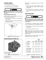
Figure 13
. Rubber Isolator & Radiator Mount
7.
Remove hoses from hydrostatic pump. Plug and
cap all fittings on hoses and pump to prevent
contamination.
8.
Remove H-drive that mounts sheave to hydrostatic
pump. Use new 1/4 x 3/4 GR5 bolts in holes
located 90° from previously occupied holes to
separate H-drive from sheave.
9.
Remove two bolts holding hydrostatic pump to
frame and remove pump from frame. Hydrostatic
pump weighs approximately 8 lbs; use care when
removing.
HYDROSTATIC PUMP INSTALLATION
1.
Position hydrostatic pump into power unit frame
and secure with two bolts. Apply Loctite
®
242 to
threads of the two mounting bolts and torque to 35
lbs-ft.
2.
Install sheave onto hydrostatic pump and secure
H-drive. Alternate tightening each cap screw to 8
lbs-ft. Align sheave with spring idler to allow for
proper belt alignment.
3.
Install hoses to hydrostatic pump.
4.
Install belts and tighten J-bolt for proper belt
tension.
5.
Install steering linkage to control arm on
hydrostatic pump.
6.
Fill hydraulic reservoir with new fluid. Use 20W-50
motor oil.
Summary of Contents for Mov'n Machine FZ25D
Page 1: ...OPERATOR S MANUAL MOW N MACHINE Rev 9 1 2015 FZ25D Power Unit MAN0646 ...
Page 30: ...30 Dealer Check Lists MAN0646 Rev 11 5 2007 NOTES ...
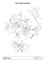
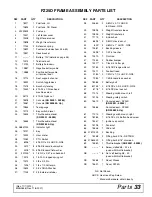
Page 32: ...32 Parts MAN0646 Rev 11 5 2007 FZ25D FRAME ASSEMBLY Rev 8 22 2008 ...
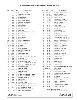
Page 34: ...34 Parts MAN0646 Rev 11 5 2007 FZ25D ENGINE ASSEMBLY Rev 6 5 2014 ...
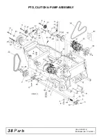
Page 38: ...38 Parts MAN0646 Rev 11 5 2007 PTO CLUTCH PUMP ASSEMBLY Rev 3 20 2013 ...
Page 42: ...42 Parts MAN0646 Rev 11 5 2007 BRAKE ASSEMBLY ...
Page 44: ...44 Parts MAN0646 Rev 11 5 2007 FZ25D WIRING DIAGRAM KUBOTA Rev 8 22 2008 ...

