Assembly
27
MAN0646 (Rev. 11/5/2007)
ASSEMBLY
DEALER SET-UP INSTRUCTIONS
Assembly of this Mow’n Machine is the responsibility of
the Woods dealer. It should be delivered to the owner
completely assembled, lubricated, and adjusted for
normal cutting conditions.
Set up the Mow’n Machine as received from the factory
with these instructions. Complete check lists on
page 29 when assembly is completed.
Power Unit Preparation
1.
Remove crating from around power unit. Remove
power unit from pallet and place on blocks.
2.
Remove Operator’s Manual from power unit frame
and save for original retail purchaser.
NOTE:
Dealer must complete and return product
registration card at time of sale.
Battery
1.
Connect ground cable to negative battery post and
secure.
2.
Confirm that rubber boot is properly secured over
positive battery post.
Lubrication/Coolant
NOTICE
■
Running engine without oil will cause engine
failure.
1.
Check oil level (30W) and the engine radiator fluid.
2.
Check that oil level (20W-50) in transmission
reservoir is full.
NOTE:
See Owner Service section for engine,
transmission, and lubrication information.
Fuel
Fill fuel tank with the correct fuel. Refer to engine man-
ual.
INSTALL DRIVE TIRES
1.
Install drive tires using five lug bolts (1) removed
from brake drum.
2.
Torque lug bolts to 85 lbs-ft.
Drive Tire Pressure:
Turf Tires
12 psi
Chevron Tires
10 - 12 psi
Figure 19
. Drive Tire Installed
ADJUST STEERING HANDLES
Figure 20
. Steering Handle Adjustment
The steering handles are shipped loose, inside the foot
rest.
1.
Remove whiz bolt (3) and lock nut (4) from left
steering lever mount (2).
2.
Position steering handle (1) to desired location on
steering lever mount (2). The top and middle holes
are for taller operators and the middle and bottom
holes are for shorter operators. Do not tighten
hardware at this time. Repeat steps 1 and 2 for
right steering handle.
3.
Rotate handles inward. Align handles with one
another. Torque all hardware to 12 lbs-ft. Make
sure handles stay in alignment.
DP5
1. Lug Bolt
1
4
3
1
2
DP8
1. Steering lever
2. Steering lever mount
3. 5/16 NC x 1 Whiz bolt
4. 5/16 Flanged lock nut
(Rev. 6/17/2013)
Summary of Contents for Mov'n Machine FZ25D
Page 1: ...OPERATOR S MANUAL MOW N MACHINE Rev 9 1 2015 FZ25D Power Unit MAN0646 ...
Page 30: ...30 Dealer Check Lists MAN0646 Rev 11 5 2007 NOTES ...
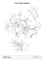
Page 32: ...32 Parts MAN0646 Rev 11 5 2007 FZ25D FRAME ASSEMBLY Rev 8 22 2008 ...
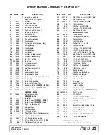
Page 34: ...34 Parts MAN0646 Rev 11 5 2007 FZ25D ENGINE ASSEMBLY Rev 6 5 2014 ...
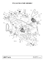
Page 38: ...38 Parts MAN0646 Rev 11 5 2007 PTO CLUTCH PUMP ASSEMBLY Rev 3 20 2013 ...
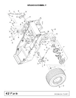
Page 42: ...42 Parts MAN0646 Rev 11 5 2007 BRAKE ASSEMBLY ...
Page 44: ...44 Parts MAN0646 Rev 11 5 2007 FZ25D WIRING DIAGRAM KUBOTA Rev 8 22 2008 ...

