background image

PART NO.

MAN0646

© 2013 Woods Equipment Company. All rights reserved. Woods

®

 and the Woods logo are trademarks of Woods Equipment Company. All other

trademarks, trade names, or service marks not owned by Woods Equipment Company that appear in this manual are the property of their respec-
tive companies or mark holders. Specifications subject to change without notice. 

Woods Equipment 

A Blount International Company

2606 South Illinois Route 2
Post Office Box 1000
Oregon, Illinois 61061

800-319-6637 tel
800-399-6637 fax
woodsequipment.com

Summary of Contents for Mov'n Machine FZ25D

Page 1: ...OPERATOR S MANUAL MOW N MACHINE Rev 9 1 2015 FZ25D Power Unit MAN0646 ...

Page 2: ... at www WoodsEquipment com or in the United States and Canada call 1 800 319 6637 The equipment you have purchased has been carefully engineered and manufactured to provide dependable and satisfactory use Like all mechanical products it will require cleaning and upkeep Lubricate the unit as specified Observe all safety information in this manual and safety decals on the equipment For service your ...

Page 3: ...S LISTS 31 BOLT TORQUE CHART 49 BOLT SIZE CHART ABBREVIATIONS 50 INDEX 51 PRODUCT WARRANTY 52 REPLACEMENT PARTS WARRANTY INSIDE BACK COVER This product contains chemicals including lead known to the State of California to cause cancer and birth defects or other reproductive harm Wash hands after handling WARNING The engine exhaust from this product contains chemicals known to the State of Californ...

Page 4: ...g your Mow n Machine Read it carefully It furnishes information and instructions that will help you achieve years of dependable performance These instructions have been compiled from extensive field experience and engineering data Some information may be general in nature due to unknown and varying operating conditions However through experience and these instructions you should be able to develop...

Page 5: ...e sure spring activated locking pin or collar slides freely and is seated firmly in tractor PTO spline groove The safety interlock system was installed for your protection Do not disconnect disable over ride or execute any action that would cause this system to malfunction If malfunction occurs stop all operation and contact dealer for repair Remove accumulated debris from this equip ment power un...

Page 6: ...only in daylight or good artificial light Keep hands feet hair and clothing away from equipment while engine is running Stay clear of all moving parts Power unit is equipped with a ROPS and seat belt Keep seat belt securely fastened during oper ation Falling off power unit can result in death from being run over or crushed Keep foldable ROPS system in locked up position during oper ation Use extre...

Page 7: ...yone else to modify or alter the equipment or any of its compo nents in any way Do not work on mower in tilt up position unless deck is in a stable position Always wear relatively tight and belted clothing to avoid getting caught in moving parts Wear sturdy rough soled work shoes and protective equipment for eyes hair hands hearing and head and respirator or filter mask where appropriate Do not wo...

Page 8: ...NDS AFTER HANDLING STORAGE Keep children and bystanders away from stor age area Never store the machine or fuel container near an open flame spark or pilot light such as on a water heater or other appliance Do not run engine indoors Exhaust gases con tain carbon monoxide an odorless and deadly poi son Remove key and store in a secure location to prevent unauthorized persons from operating SAFETY R...

Page 9: ...0646 7 6 2007 SAFETY INSTRUCTIONAL DECALS ATTENTION BECOME ALERT YOUR SAFETY IS INVOLVED Replace Immediately If Damaged 1 PN 72407 2 PN 72404 3 SERIAL NUMBER PLATE Safety Decals continued on next page Rev 6 17 2013 ...

Page 10: ...nder edges of decals causing them to peel or come off Replacement safety decals can be ordered free from your Woods dealer To locate your nearest dealer check the Dealer Locator at www woodsequipment com or in the United States and Canada call 1 800 319 6637 6 PN 70376 CAUTION ENGINE COOLANT SEE ENGINE MANUAL DO NOT OPEN WHEN HOT 72648 5 PN 72648 9 PN 07754100 10 PN 72801 07754100 SAFETY INSTRUCTI...

Page 11: ...r drugs Keep hands feet hair and clothing away from equipment while engine is running Stay clear of all moving parts Never allow riders on power unit or attachment Never direct discharge toward people animals or property Moving steering levers rapidly from forward to reverse or reverse to forward could cause loss of control Look down and to the rear and make sure area is clear before operating in ...

Page 12: ...o provide notification If tem perature light starts to flash during operation discon tinue operation The light is programed to flash at 220 fahrenheit and above NOTE The radiator and prescreen require regular cleaning to prevent engine overheating Clean the pre screen daily and the radiator fins every 40 hours Do not use high pressure on radiator fins to avoid radiator damage HOUR METER The hour m...

Page 13: ...r for starting than leftover fuel STARTING MOWER OR ATTACHMENT Make sure people and objects are clear of attachment and discharge area before engaging PTO NOTICE Never engage PTO if the mower blades are plugged with grass or other material This may cause damage to the electric clutch 1 With engine running position throttle at half speed 2 Engage PTO by pulling up on the PTO switch 3 Move throttle ...

Page 14: ...will move the power unit in reverse The further forward or rearward the steering handles are moved the faster the machine will move Steering Handle Positions NOTICE If you become confused during operation return both handles to the center neutral position and the power unit will stop Forward Both handles forward Reverse Both handles rearward Gentle Right Left handle further forward than right Gent...

Page 15: ...ve using a 5 8 wrench or round punch WEIGHT TRANSFER When using weight transfer system correct counterweight must be used to maintain stability See counterweight chart in power unit manual or contact dealer The weight transfer is designed to place an additional load on the drive wheels providing additional traction 1 Attach mower to power unit and set to desired cutting height 2 Torque bolt on bot...

Page 16: ...ttention to the cooling fins gover nor parts and muffler ___ Do not allow riders ___ Inspect area and remove stones branches or other hard objects that might be thrown causing injury or damage ___ Clean air intake screen Check air cleaner ser vice if necessary ___ Clean area around oil fill dipstick Remove dip stick and check to be sure oil is in operating range between marks on dipstick Add oil i...

Page 17: ...empt to check oil level while engine is running Serious injury or damage to equipment could result 1 Park power unit on a level surface 2 Stop engine and clean off dirt and dust from around dipstick 3 Remove dipstick check oil level Oil level should be between marks on dipstick Avoid touching exhaust manifold if unit has been running 4 Add oil as necessary Change Engine Oil NOTICE Use care to prev...

Page 18: ...OTE Proper bearing adjustment is essential to good bearing life If bearings are loose caster wheels will wobble and or slap side to side If bearings are over tightened loosen hex nut and rap shaft with a lead hammer to loosen bearings Readjust bearings until proper setting is obtained Figure 7 Tailwheel Assembly Typical Lubrication Service Intervals 1 Hydrostatic Fluid Level check 8 hours 2 Deck P...

Page 19: ...er or when operating in ambient temperature above 100 F for any extended period 1 Place power unit on a level surface 2 Stop engine remove key 3 Remove case drain hose fitting from bottom of reservoir located outside of power unit frame Allow reservoir to completely drain 4 Remove automotive type filter Figure 8 by turning counter clockwise 5 Replace filter by turning until gasket is seated then t...

Page 20: ...accumulated debris from this equip ment power unit and engine to avoid fire hazard CLEANING After Each Use Remove large debris such as clumps of dirt grass crop residue etc from machine Inspect machine and replace worn or damaged parts Replace any safety decals that are missing or not readable Periodically or Before Extended Storage Clean large debris such as clumps of dirt grass crop residue etc ...

Page 21: ... leaks from excess fluid expansion 3 Make sure dump valves are tightened down NOTE Transmission fluid can leak by the dump valve if by pass is not tight Tighten hex head if dump valves are loose No Positive Neutral Position If drive wheels travel forward or reverse when steering handles are in the NEUTRAL position pivoted out ward adjustment of hydrostatic pumps is necessary 1 Block up power unit ...

Page 22: ...d be connected to the main wire harness underneath the seat pan by the left hand steering pivot linkage if there is not a deck or a standard deck is attached If using the power tilt option and you need to check the deck safety switch refer to Figure 12 and troubleshooting deck safety switch If the deck switch is open the engine will kill when pulling handles in 3 Check park brake switch If there i...

Page 23: ...move belt 6 If clearance between radiator cowl and engine sheave is too tight loosen or remove rubber isolator 84 radiator mount located above the engine Push radiator forward until belt clears radiator cowl and engine sheave Figure 13 Rubber Isolator Radiator Mount 7 Remove hoses from hydrostatic pump Plug and cap all fittings on hoses and pump to prevent contamination 8 Remove H drive that mount...

Page 24: ...le linkage NOTE Approximately 12 to 13 lbs of force at the top of the handle is needed to apply the single brake 4 Reconnect right parking brake rod 5 Disconnect clevis from left parking brake and brake handle linkages 6 Adjust right parking brake pull rod until brake rock shaft lug is perpendicular with the bottom edge of the frame rail 7 Reconnect parking brake rod NOTE Approximately 24 to 26 lb...

Page 25: ...blue on threads of cap screw before installing 4 Torque Grade 8 cap screw 21 to 40 lbs ft 5 Check belt alignment and if necessary adjust PTO sheave on shaft See NOTE If belt alignment is not necessary proceed to Reassemble Components Figure 17 Align Clutch PTO Sheave Align Belt 6 Loosen the taper bolts 13 adjust sheave 2 and tighten bolts to 85 lbs inch Reassemble Components 1 Install PTO V belts ...

Page 26: ...comply with these safety mes sages before returning unit to operation Make sure all safety decals are installed Replace if damaged See Safety Decals section for location Make sure shields and guards are properly installed and in good condition Replace if damaged 16 19 22 2 2 PTO sheave 16 Cable clutch stop 19 Electric clutch mag stop 1 1 8 22 PTO V belt set matched WARNING ...

Page 27: ...uid 2 Check that oil level 20W 50 in transmission reservoir is full NOTE See Owner Service section for engine transmission and lubrication information Fuel Fill fuel tank with the correct fuel Refer to engine man ual INSTALL DRIVE TIRES 1 Install drive tires using five lug bolts 1 removed from brake drum 2 Torque lug bolts to 85 lbs ft Drive Tire Pressure Turf Tires 12 psi Chevron Tires 10 12 psi ...

Page 28: ...teering stop bolt on the left Figure 21 Left Side Steering Stop Bolts INSTALL SINGLE TAILWHEEL OPTIONAL 1 Attach tailwheel spacer 22 and pivot mount adapter 1 to rear of power unit frame using two cap screws 21 and lock nuts 20 2 Attach pivot housing 2 to pivot mount adapter and power unit frame using four cap screws 18 and lock washers 19 3 Torque hardware to 35 lbs ft NOTE Rear tire pressure 18 ...

Page 29: ...s operation including hydrostatic neutral and safety switch system page 12 ___ Check all fluid levels See Owner Service section ___ Check tire pressure See Assembly section DELIVERY CHECK LIST DEALER S RESPONSIBILITY ___ Show customer how to make adjustments ___ Instruct customer how to lubricate and explain importance of lubrication ___ Point out the safety decals Explain their meaning and the ne...

Page 30: ...30 Dealer Check Lists MAN0646 Rev 11 5 2007 NOTES ...

Page 31: ... 37 PTO PUMP CLUTCH ASSEMBLY 38 39 SEAT ASSEMBLY 40 TAILWHEEL ASSEMBLY Single Tailwheel Assembly 41 Wide Stance Tailwheel Assembly 41 BRAKE ASSEMBLY 42 43 WIRING DIAGRAM KUBOTA DIESEL 44 45 STEERING ASSEMBLY 46 COUNTERWEIGHT MOUNT KIT OPTIONAL 47 HEADLIGHT KIT OPTIONAL 48 Parts Index Mow n Machine FZ25D ...

Page 32: ...32 Parts MAN0646 Rev 11 5 2007 FZ25D FRAME ASSEMBLY Rev 8 22 2008 ...

Page 33: ...3 8 x 3 4 Pin 35 1326 2 1 8 x 1 2 Cotter pin 36 70624 2 3 4 x 18GA Washer 37 71145 2 3 4 External retainer REF PART QTY DESCRIPTION 38 24660 2 3 8 NC x 3 1 2 HHCS full thread GR5 39 73896 4 Weight transfer sleeve 40 73895 2 Weight transfer pin 41 71170 2 5 Link chain 42 6698 4 3 8 NC Hex lock nut 43 839 4 3 8 NC x 1 HHCS GR5 44 73581 2 Bushing sleeve 45 3598 2 1 2 Flat washer 46 72410 1 Pivot rod ...

Page 34: ...34 Parts MAN0646 Rev 11 5 2007 FZ25D ENGINE ASSEMBLY Rev 6 5 2014 ...

Page 35: ... screw 40 2472 16 5 16 Standard lock washer 41 10 M10 x 1 25 x 20 mm HHCS CL 8 8 42 838 14 3 8 Standard lock washer REF PART QTY DESCRIPTION 43 307125 6 M8 x 1 25 x 20 mm HHCS CL 8 8 44 30515 4 M8 x 1 25 Hex nut 47 300057 11 1 4 NC x 3 4 HHCS GR5 48 6128 15 1 4 NC Lock nut 51 839 7 3 8 NC x 1 HHCS GR5 52 15041 4 1 4 NC x 1 1 2 HHCS GR5 53 9 M8 x 1 25 x 15 mm Socket head cap screw 54 62259 2 2 Hose...

Page 36: ... 3 4 JICM x 3 4 ORBM 12 75482 1 Hose assembly suction 13 75483 1 Hose assembly Case drain 15 316016 4 Adapter 3 4 JICM x 7 8 ORBM REF PART QTY DESCRIPTION 16 315031 2 Adapter 9 16 ORBM x 3 4 JICM 17 62367 2 Elbow 9 16 ORBM x 9 16 JIMCM 19 75481 1 Hose Right top pump front motor 20 75480 1 Hose Right bottom pump back motor 21 75478 1 Hose Left top pump back motor 22 75479 1 Hose Left bottom pump fr...

Page 37: ...1 6 Adapter 3 4 JICM x 3 4 ORBM 12 75482 1 Hose assembly suction 13 75483 1 Hose assembly Case drain 15 316016 4 Adapter 3 4 JICM x 7 8 ORBM REF PART QTY DESCRIPTION 17 62367 2 Elbow 9 16 ORBM x 9 16 JIMCM 19 75481 1 Hose Right top pump front motor 20 75480 1 Hose Right bottom pump back motor 21 75478 1 Hose Left top pump back motor 22 75479 1 Hose Left bottom pump front motor Standard hardware ob...

Page 38: ...38 Parts MAN0646 Rev 11 5 2007 PTO CLUTCH PUMP ASSEMBLY Rev 3 20 2013 ...

Page 39: ...98 5 3 8 NC Center lock nut 25 31138 2 3 8 NC x 3 1 2 HHCS GR5 26 73416 2 Idler sleeve 27 75362 1 PTO Idler arm includes item 42 REF PART QTY DESCRIPTION 28 75585 1 Debris screen 29 75587 1 19 5 Trim Lok 30 75588 1 3 75 Trim Lok 31 75476 1 Sheave pump idler 32 73826 2 Extension spring 33 75551 1 Spring lug 34a 75402 1 Drive V belt Parker 34b 78755 1 Drive V belt Hydro Gear 35a 75543 1 Pump Left Pa...

Page 40: ...Foam seal 80 22 21341 4 5 8 NC x 3 1 4 HHCS GR5 23 1032106 1 FZ ROPS Assembly 24 78494 1 Kit arm rest RH REF PART QTY DESCRIPTION 25 78495 1 Kit arm rest LH 26 78500 1 Kit cushion cover 27 78501 1 Kit back seat cushion 28 78503 1 Kit track 29 78496 1 Arm pad 30 75502 1 Switch 31 75503 1 Plunger 32 75504 1 Spring 33 75532 Trim lock 41 25 36 1025871 Knob seat adjustment NS 37 75368 1 Decal Woods NS ...

Page 41: ...GR5 19 838 4 3 8 Lock washer 20 6698 2 3 8 NC Lock nut 21 920 2 3 8 NC x 1 3 4 HHCS GR5 22 78058 2 Tailwheel spacer REF PART QTY DESCRIPTION 3 3585 4 Bearing cup 4 3586 4 Bearing cone 5 70328 2 Seal 1 5 x 2 x 187 6 70086 2 Spacer 375 x 1 7 73818 2 Wheel fork 8 05435700 4 Bearing 25mm x 52mm x 15mm 9 3598 4 1 2 Flat washer 10 07147800 2 Wheel tire assembly 15 x 6 6 11 09231800 2 Spacer wheel 12 765...

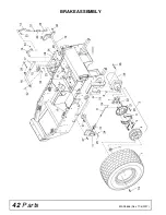
Page 42: ...42 Parts MAN0646 Rev 11 5 2007 BRAKE ASSEMBLY ...

Page 43: ...C x 5 8 HHCS GR5 21 2472 8 5 16 Standard lock washer 22 5248 8 5 16 NC x 1 1 4 SHCS 23 2985 1 1 4 28 Tapered thread grease fitting 24 3145 6 3 32 x 1 2 Cotter pin 25 70024 3 Clevis pin 26 3231 1 3 8 NC x 2 HHCS GR5 27 12169 7 3 8 NC x 1 1 4 HHCS GR5 28 6698 8 3 8 NC Hex lock nut 29 835 1 3 8 NC Hex nut 30 35709 2 10 24 x 3 4 Pan head machine screw 31 35710 2 10 24 Nylok nut 32 4115 1 3 16 x 1 1 8 ...

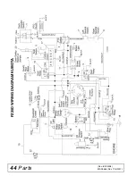
Page 44: ...44 Parts MAN0646 Rev 11 5 2007 FZ25D WIRING DIAGRAM KUBOTA Rev 8 22 2008 ...

Page 45: ...ring safety switch left 71314 1 Left steering switch mount 8 75502 1 Seat switch 9 73902 1 Hour meter 10 71475 3 Relay 11 71148 1 Brake switch REF PART QTY DESCRIPTION 12 71385 1 Fuse 30 Amp auto 13 71387 1 Fuse 7 5 Amp auto 15 72314 1 Water temperature sender 17 75437 1 Timer delay 17A 10 x 7 16 Self tapping screw NS 18 74079 1 Ground strap 19 75533 1 Cable alternator starter FZ25D 20A 75521 1 Ca...

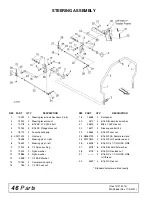
Page 46: ...sher 12 72886 4 Nylon washer 13 3598 2 1 2 SAE Washer 14 70162 2 Compression spring 15 765 4 1 2 NC Lock nut REF PART QTY DESCRIPTION 18 75488 2 Dampener 20 2472 4 5 16 Standard lock washer 21 30515 4 M8 x 1 25P Hex nut 22 75511 2 Steering control link 23 33654 2 5 16 NF Jam nut 24 08960700 2 5 16 NF RH Female rod end 25 09107800 2 5 16 NF LH Female rod end 26 24408 4 5 16 NC x 1 1 2 HHCS GR5 27 4...

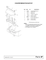
Page 47: ...ed for your mower and equipment Not included in kit As required REF PART QTY DESCRIPTION A 70980 Counterweight mount kit 1 71063 1 Weight mount 2 71123 1 Weight strap 3 71156 2 375 16 x 6 Hook bolt 4 839 4 3 8 NC x 1 HHCS 5 66885 4 3 8 NC Flange nut 6 71512 50 lb Counterweight A R 7 565 2 3 8 Flat washer 8 838 2 3 8 Lock washer Standard hardware obtain locally ...

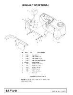
Page 48: ...TY DESCRIPTION A 73938 Headlight kit 1 73937 1 Light bracket left 2 73936 1 Light bracket right 3 73935 2 Rect work light with switch 4 07516000 4 Button bumper 5 6096 4 5 16 NC x 3 4 HHCS 6 2472 4 5 16 Lock washer 7 4378 4 5 16 Flat washer 8 5288 2 1 4 NC Hex nut 9 1985 2 1 4 Lock washer 10 8 Plastic tie Standard hardware obtain locally ...

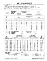
Page 49: ...1 1 2 467 634 722 979 1020 1383 Diameter Thread Pitch Millimeters Wrench Size COARSE THREAD FINE THREAD Diameter Thread Pitch Millimeters MARKING ON HEAD MARKING ON HEAD Metric 8 8 Metric 10 9 Metric 8 8 Metric 10 9 N m lbs ft N m lbs ft N m lbs ft N m lbs ft 6 x 1 0 10 mm 8 6 11 8 8 6 11 8 6 x 1 0 8 x 1 25 13 mm 20 15 27 20 21 16 29 22 8 x 1 0 10 x 1 5 16 mm 39 29 54 40 41 30 57 42 10 x 1 25 12 x...

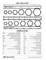
Page 50: ...c HHCS Hex Head Cap Screw HT Heat Treated JIC Joint Industry Council 37 Degree Flare LH Left Hand LT Left m Meter mm Millimeter M Male MPa Mega Pascal N Newton NC National Coarse NF National Fine NPSM National Pipe Straight Mechanical NPT National Pipe Tapered NPT SWF National Pipe Tapered Swivel Female ORBM O Ring Boss Male P Pitch PBY Power Beyond psi Pounds per Square Inch PTO Power Take Off QD...

Page 51: ...2 Manual Fuel Shut Off Valve 15 Moving Disabled Tractor 15 Owner Pre Operation Check List Owner s Responsibility 16 Practice Operation 13 Safety Switch System 12 Start Mower or Attachment 13 Stop Mower or Attachment 13 Starting Engine 13 Steering Handle Operation 14 Steering Handle Operation Diagram 14 Steering Handle Positions 14 Stopping Engine 15 Uneven Terrain Operation 13 Weight Transfer 15 C...

Page 52: ...3 Repairs made with parts other than those obtained through WOODS WOODS makes no warranty express or implied with respect to engines batteries tires or other parts or accessories with respect to which the manufacturer provides a separate warranty WHAT WOODS WILL DO TO CORRECT PROBLEMS WOODS obligation under this Warranty is limited to at WOODS option the repair or replacement free of charge of the...

Page 53: ...items or any damage failure or loss caused by improper operation improper maintenance misuse or an accident WOODS obligation under this Warranty is limited to at WOODS option the repair or replacement free of charge of the product if the product is defective or in noncompliance with this Warranty The product must be returned to WOODS with proof of purchase within thirty 30 days after such defect o...

Page 54: ...s or service marks not owned by Woods Equipment Company that appear in this manual are the property of their respec tive companies or mark holders Specifications subject to change without notice Woods Equipment A Blount International Company 2606 South Illinois Route 2 Post Office Box 1000 Oregon Illinois 61061 800 319 6637 tel 800 399 6637 fax woodsequipment com ...

Reviews: