Dealer Service
23
MAN1192 (1/13/2017)
Troubleshooting Deck Safety Switch
1.
Pull handlebars in with deck in lowest cutting
height position (1), see Figure 10.
2.
Check that switch is making contact with the height
gauge.
3.
Check that the wires are properly hooked up to
power unit.
4.
Adjust switch bracket location on actuator if
needed (four screws). Make sure height screw
does not bottom out on slot in either direction when
raising or lowering deck.
5.
Check that screws holding switch to bracket are
not too tight and holding lever open.
6.
Adjust safety switch lever or replace switch if
necessary.
7.
After adjustments, check that engine cuts out with
deck partially raised.
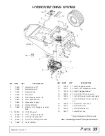
HYDROSTAT DRIVE REMOVAL
1.
Place power unit on a level surface and remove
key.
2.
Place power unit on stands to allow access to
bottom of the machine and remove drive wheels.
3.
Remove brake linkage from control arm on
hydrostat.
4.
Remove brake arm actuator and spring from brake
arm.
5.
Remove expansion tank hose from hydro.
6.
Loosen idler spring and remove belt.
7.
Remove two outer screws, washers and nuts.
8.
At front of machine, remove two screws and nuts
attaching small L bracket.
9.
At rear of machine, remove two screws and nuts
attaching small L bracket.
10.
While supporting hydro (each hydro weighs
approximately 33 pounds), remove front and rear
screws and nuts.
11.
Lower hydro down and out from under unit.
12.
For repair parts information, contact Hydro-Gear
®
at 1-877-728-7410 for nearest authorized dealer.
HYDROSTAT DRIVE INSTALLATION
1.
Position hydro under frame and carefully raise up
into position.
2.
Install two outer screws, washers and nuts finger
tight.
3.
Install small L bracket at the front and rear using
long bolts through frame loosely.
4.
Install screws and nuts in the front and rear of the
frame finger tight.
5.
With hydro positioned squarely, tighten small L
bracket nuts and then the longer screws through
frame.
6.
Tighten outer nuts.
7.
Install belt and tighten spring to proper belt tension.
8.
Install expansion tank hose.
9.
Install brake arm actuator and spring on brake arm.
No adjustment necessary if arm was not moved.
10.
Install brake linkage from control arm to hydrostat.
11.
Proceed to oil change maintenance for proper oil
change and pump purging.
BELT REMOVAL
1.
Remove key from switch.
2.
Loosen idler spring bolt, and derail belt from
pulleys.
3.
Remove belts.
ENGINE REMOVAL
1.
Disconnect throttle cable, battery cables, hoses,
fuel line, and electrical wires from engine.
2.
Remove the four engine mounting bolts from
bottom of power unit frame.
3.
Remove belts from the engine pulleys. See Belt
Removal.
4.
Remove exhaust.
5.
Lift engine from the power unit frame.
NOTE:
Contact your authorized engine dealer for
parts and repairs.
PARKING BRAKE ADJUSTMENT
NOTE:
Hydrostatic system parking brake is similar to
automotive style parking pawl and is not a service
brake. Brake system is for parking of unit and emer-
gency use only. The drive wheel may have to rotate
slightly to engage pawl in locking ring (usually less the
3 degrees of wheel rotation).
NOTE:
Parking brake is adjusted from the factory and
should require no maintenance unless the system parts
are replaced.
NOTE:
Adjust right and left brakes individually.
1.
With drive wheels off of the ground and brake
handle is in ON position, check to see if drive
wheel rotates.
2.
If drive wheel rotates and park brake does not
engage, remove screw from top of park brake
release link and free park brake release rod. (If
Summary of Contents for MOW'N MACHINE FZ22-2
Page 1: ...OPERATOR S MANUAL MOW N MACHINE MAN1192 1 13 2017 FZ22 2 TM ...
Page 28: ...28 Dealer Check Lists MAN1192 1 13 2017 NOTES ...
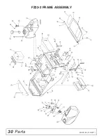
Page 30: ...30 Parts MAN1192 1 13 2017 FZ22 2 FRAME ASSEMBLY ...
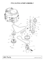
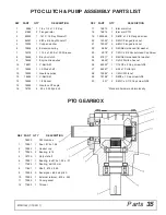
Page 34: ...34 Parts MAN1192 1 13 2017 PTO CLUTCH PUMP ASSEMBLY ...
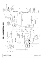
Page 38: ...38 Parts MAN1192 1 13 2017 FZ22 2 WIRING DIAGRAM ...


