Owner Service
19
MAN0999 (12/4/2012)
FLUID CHANGE PROCEDURE
This transaxle is designed with an external filter for
ease of maintenance. To ensure constant fluid quality
levels and longer life, an initial oil and filter change at
75-100 hours, then every 400 hours thereafter is rec-
ommended.
The following procedure can be performed with the
transaxles installed in the vehicle, and the vehicle on
level ground. Apply the bypass valve for each transaxle
and lock the vehicle parking brake.
1.
Remove the three 1/4" filter guard screws and filter
guard. Clean any loose debris from around the
perimeter of the filter.
2.
Place an oil drain pan (12" or more diameter and 8
qt. capacity is optimal) beneath the oil filter.
Remove the oil filter from the transaxle.
3.
After the oil has drained, wipe the filter base
surface off and apply a film of new oil to the gasket
of the new replacement filter (part number 78726).
4.
Install the new filter by hand; turn 3/4 to one full
turn after the filter gasket contacts the filter base
surface.
5.
Re-install the filter guard with three 1/4" screws.
Torque each screw to 65 in. lbs. (7.3 Nm).
6.
Repeat steps 1-5 on the opposite side transaxle
drive.
7.
Drain old oil filters of all free flowing oil prior to
disposal. Place used oil in appropriate containers
and deliver to an approved recycling collection
facility.
8.
Remove the top port plug from the left side and
right side transaxles prior to filling with oil. This will
allow the transaxles to vent during oil fill.
9.
Remove the cap from the transaxle's expansion
tank located on the vehicle frame.
10.
Fill with 20W50 motor oil until oil just appears at the
bottom of each transaxle's top port (approximately
2 qts. per transaxle, 4 qts. total). Install the top port
plug into each transaxle as the oil level reaches
this port.
11.
Install and torque the top port plugs to 180 in. lbs.
(20.3 Nm).
12.
Continue to fill the transaxles through the
expansion tank until the "Full Cold" line is reached
on the Hydro-Gear
®
expansion tank. An additional
.5 qt will be needed to fill expansion tank.
13.
Re-install the expansion tank cap by hand. Be
careful to not over tighten.
14.
Proceed to the purge procedure.
PURGING PROCEDURES
Due to the effects air has on efficiency in hydrostatic
drive applications, it is critical that it is purged from the
system.
Air creates inefficiency because its compression and
expansion rate is higher than that of the oil approved
for use in hydrostatic drive systems.
These purge procedures should be implemented any
time a hydrostatic system has been opened to facilitate
maintenance or the oil has been changed.
The resulting symptoms in hydrostatic systems may
be:
1.
Noisy operation.
2.
Lack of power or drive after short term operation.
3.
High operation temperature and excessive
expansion of oil.
Before starting, make sure the transaxle is at the
proper oil level. If it is not, fill to the specifications out-
lined in this manual.
The following procedures are best performed with the
vehicle drive wheels off the ground. Then repeat under
normal operating conditions. If this is not possible, then
the procedure should be performed in an open area
free of any objects or bystanders.
1.
Disengage the brake if activated.
2.
With the bypass valve open and the engine
running, slowly move the directional control in both
forward and reverse directions (5 or 6 times).
3.
With the bypass valve closed and the engine
running, slowly move the directional control in both
forward and reverse directions (5 to 6 times).
Check the oil level, and add oil as required after
stopping the engine.
4.
It may be necessary to repeat Steps 2 and 3 until
all the air is completely purged from the system.
When the transaxle operates at normal noise
levels and moves smoothly forward and reverse at
normal speeds, then the transaxle is considered
purged.
Summary of Contents for MOW'N MACHINE FZ22K
Page 1: ...OPERATOR S MANUAL MOW N MACHINE MAN0999 Rev 11 7 2013 FZ22K TM...
Page 28: ...28 Dealer Check Lists MAN0999 12 4 2012 NOTES...
Page 30: ...30 Parts MAN0999 12 4 2012 FZ22K FRAME ASSEMBLY Rev 2 18 2013...
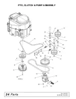
Page 34: ...34 Parts MAN0999 12 4 2012 PTO CLUTCH PUMP ASSEMBLY Rev 2 18 2013...
Page 38: ...38 Parts MAN0999 12 4 2012 FZ22K WIRING DIAGRAM...

