28 Dealer Service
20944 (Rev. 2/3/2006)
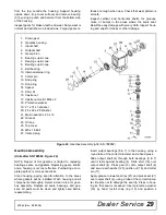
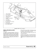
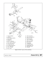
Figure 23. Gearbox Assembly (SN 788882 and Prior)
Gearbox Disassembly
(Units after S/N 788882, Figure 24)
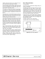
Remove gearbox from cutter as follows: Disconnect
and remove the rear driveline from the gearbox.
Remove vent plug (27) and siphon gear lube from
housing through this opening. Remove cotter pin,
washer, and nut from vertical shaft and remove cross-
bar. Remove the four bolts that hold the gearbox on the
cutter.
Remove 3/8" plug from side of gearbox and pour out
gear oil.
Remove oil cap (23) (to be replaced), snap ring (12),
and shim (15) from input shaft (3).
Support gearbox in hand press and push on the input
shaft (3) to remove bearing (9) and spacer (14).
Remove top cover (25) from housing and gear (1) from
inside housing.
Remove oil seal (22) from front of housing (to be
replaced). Remove snap ring (12) and shim (15) from
front of housing.
Support housing in vise in a horizontal position. The
castle nut (17), cotter pin (28), washer (18), and hub
(24) are already removed with the stump jumper/cross-
bar. Remove the snap ring (10), washer (19), and seal
(21).
Remove cotter pin (11), castle nut (16), and washer
(20) from output shaft (4). Remove output shaft by
using a punch and hammer; tap on the top to drive
down.
Remove gear (5) and shim (15) from inside housing.
Remove bearing (7) by using a punch and hammer
1.
1.38 x 2.56 x .38" Seal
2.
Retaining ring
3.
Shim washer kit
4.
Bearing cup
5.
Bearing cone
6.
30-Tooth gear and horizontal shaft
7.
Bearing cone
8.
Bearing cup
9.
3/8" Lock washer
10.
3/8 x 3/4" Bolt
11.
1" Vented pipe plug (used prior to S/N 2000)
12.
Gearbox cover
13.
Housing
14.
17-Tooth gear and vertical shaft
15.
Bearing cone
16.
Bearing cup
17.
O-Ring
18.
Double lip seal
19.
Stake nut
20.
Puller
21.
Puller bolts
22.
Dipstick (used on SN 2000-788882)
23.
O-Ring (used on SN 2000-7888882)


