Assembly 37
20944 (Rev. 2/3/2006)
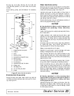
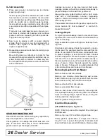
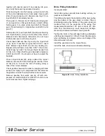
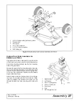
Figure 32. Optional Hydraulic Cylinder Installation for P990-3
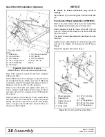
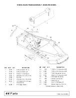
Optional Front Roller Installation for
RM990-3 and P990-3
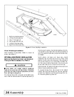
The optional front roller is designed to carry the center
of the mower over uneven ground, minimizing scalping.
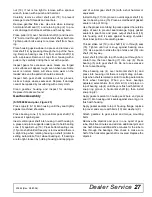
Front roller mounting brackets use the four mounting
bolts of the gear stand.
Remove the gear stand front mounting bolts. Hole pat-
terns in the mounting brackets (1 & 2) determine right
and left. Position these brackets with the highest hole
to the rear, the middle hole forward, and the bracket
angle outward as shown.
Attach brackets with the carriage bolts (3) and flange
lock nuts (7) provided with the front roller kit. Place
roller (5) between the brackets and insert rod (6)
through brackets and roller, securing with cotter pins
(4).
1.
3-1/2 x 8" Single-acting hydraulic cylinder
2.
Transport bar
3.
Lock-up pin
4.
1/4 x 1-3/4" Cotter pin
5.
1 x 2" x 10 GA Flat washer
6.
3/16" Safety pin
1.
Right bracket
2.
Left bracket
3.
3/8 x 1" Carriage bolt
4.
3/16 x 1" Cotter pin
5.
Front roller
6.
Rod
7.
3/8" Flanged lock nut
(Rev. 1/21/2010)

