background image

Assembly 39

20944 (Rev. 2/3/2006)

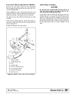
Rear Caster Wheel Installation for RM990-3 

Remove the rear caster wheel and arm assemblies
from shipping location along the inner deck rails. Dis-
card the shipping bolts.

Attach adjustment lugs to frame with bolts (36), lock
washers (37) and nuts (38). Attach caster wheel arm to
frame with bolt (36), lock washer (37) and nuts (38).

The wheel comes assembled with bearings and cups
installed.

Adjust mower cutting height by using chart (page 11)
and secure with bolts (32) and nuts. Tighten all hard-
ware (see page 43).

Repeat for opposite rear caster wheel.

 Figure 35. RM990-3 Rear Caster Wheel Installation

Initial Filling of Gearbox

NOTICE

■  

Gearbox was not filled with oil at the factory. It

must be serviced before operating. Failure to ser-
vice will result in damage to gearbox.

The gearbox was not filled at the factory. Remove the
fill plug and pour in one quart of SAE 90W gear lube,
wait five minutes and add an additional pint and one
half. Allow an additional five minutes for the lube to flow
through the bearings, then check to make sure half of
the horizontal gear shaft is covered. Replace the fill
plug.

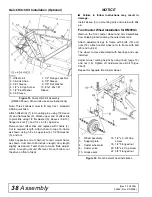
1.

Support plate

2.

Caster wheel arm

12. Tire

13. Caster yoke

32. 1/2" x 3-3/4 Cap screw

34. 1/2" Flange lock nut

36. 5/8" x 4 Cap screw

38. 5/8" Hex nut

(Rev. 3/14/2008)

Summary of Contents for P990-3

Page 1: ...OPERATOR S MANUAL REARMOUNT MOWERS 20944 Rev 1 21 2010 Tested Proven Unbeatable RM990 3 P990 3...

Page 2: ...Dealer Locator at www WoodsEquipment com or in the United States and Canada call 1 800 319 6637 The equipment you have purchased has been carefully engineered and manufactured to provide dependable a...

Page 3: ...STS 41 BOLT TORQUE CHART 63 BOLT SIZE CHART ABBREVIATIONS 64 INDEX 65 REPLACEMENT PARTS WARRANTY INSIDE BACK COVER PRODUCT WARRANTY BACK COVER Rev 3 14 2008 This Operator s Manual should be regarded a...

Page 4: ...ance These instructions have been compiled from extensive field experience and engineering data Some information may be general in nature due to unknown and varying operating conditions However throug...

Page 5: ...power unit and engine to avoid fire hazard Make sure all safety decals are installed Replace if damaged See Safety Decals section for location Make sure shields and guards are properly installed and...

Page 6: ...g in reverse Do not operate or transport on steep slopes Do not operate or transport equipment while under the influence of alcohol or drugs MAINTENANCE Before dismounting power unit or performing any...

Page 7: ...elt Keep foldable ROPS systems in locked up position at all times Buckle Up Keep seat belt securely fastened Allow no riders RAISED EQUIPMENT CAN DROP AND CRUSH Before working underneath follow all in...

Page 8: ...D SERIOUS INJURY OR DEATH Read Operator s Manual available from dealer and follow all safety precautions Keep all shields in place and in good condition Operate mower from tractor seat only Lower mowe...

Page 9: ...y Keep guards in place and in good condition BLADE CONTACT OR THROWN OBJECTS CAN CAUSE SERIOUS INJURY OR DEATH DANGER 15503 C GUARD MISSING DO NOT OPERATE DANGER 33347E DANGER DANGER GUARD MISSING DO...

Page 10: ...age before resuming operation Always wear relatively tight and belted clothing to avoid getting caught in moving parts Wear sturdy rough soled work shoes and protective equipment for eyes hair hands h...

Page 11: ...2 Measure from bottom of straightedge to the ground at locations A and B Subtract 5 from mea surement B to determine cutting height For best mowing results adjust the front of the mower slightly lowe...

Page 12: ...fety chain to attachment and tractor Raise mower tongue to tractor drawbar height with jack provided and attach with a 3 4 or larger high strength drawbar pin Retain pin to keep it in place Connect mo...

Page 13: ...tight Replace any damaged hoses immediately ___ Raise and lower equipment to make sure air is purged from hydraulic cylinders and hoses ___ Make sure tractor ROPS or ROPS CAB and seat belt are in goo...

Page 14: ...und and scalp An optional front roller may be installed to minimize scalping Uneven Terrain Do not operate or transport on steep slopes Do not stop start or change directions sud denly on slopes Use e...

Page 15: ...Extended Storage Clean large debris such as clumps of dirt grass crop residue etc from machine Remove the remainder using a low pressure water spray 1 Be careful when spraying near scratched or torn s...

Page 16: ...draulic cylin der When the optional hydraulic cylinder is installed the standard equipment transport bar must be pinned in the raised position With either the ratchet adjust ment link or the optional...

Page 17: ...ase gun Insert the needle point into the bearing hole and apply one good pump Figure 9 Lubrication Points Ref No Description Frequency 1 Front U Joint 8 Hours 2 Rear U Joint 8 Hours 3 Gearbox Cover ha...

Page 18: ...sure belt is on drive pulley A and route belt around spring loaded idler C 6 Grasp belt between spindle pulley B spring loaded idler C and spindle pulley D Pull spring loaded idler with belt and route...

Page 19: ...intain balance on both blades from a spindle by grinding the same amount from them Blades that vary excessively in weight can cause vibration Figure 12 Blade Sharpening Blade Removal This mower is equ...

Page 20: ...hat part of grass pressed down by path of tractor tires Slow ground speed of tractor but keep engine running at full PTO rpm Dull blades Sharpen or replace blades Material discharge from mower unevenl...

Page 21: ...lt misaligned or belt rubbing guide Re align belt or guide be sure belt does not rub any other part while running Pulley misalignment Inspect to ensure belt is running in center of backside idler shim...

Page 22: ...arm anti sway mechanisms to prevent side to side move ment For the pull type unit raise mower with the standard ratchet adjustment link or the optional hydraulic cylin der When the optional hydraulic...

Page 23: ...that is too small will bow seal cage Carefully press seal into housing preventing distortion to metal seal cage Seal should seat firmly and squarely against machined housing shoulder Make sure seal l...

Page 24: ...es of pulley and tighten alternately to 12 lbs ft securing pul ley to bushing Reinstall blades and belt WHEEL SPINDLE REPAIR For Pull Type Mowers Only Wheel spindle repair is accomplished in a manner...

Page 25: ...drive in vise hold yoke in hand and tap on yoke to drive cup up out of yoke See Figure 19 Figure 19 3 Clamp cup in vise as shown in Figure 20 and tap on yoke to completely remove cup from yoke Repeat...

Page 26: ...non toxic degreasing agent or commercial detergent and water Be sure to clean pulley grooves The sealants recommended for gearbox repair are Per matex Aviation 3D Form A Gasket or Loctite 515 Gasket...

Page 27: ...housing on shaft similar to setting automobile front wheel bearings If bearings are too tight loosen by holding housing and rapping on end of vertical gear shaft 14 with a shot hammer or equivalent In...

Page 28: ...to be replaced Remove snap ring 12 and shim 15 from front of housing Support housing in vise in a horizontal position The castle nut 17 cotter pin 28 washer 18 and hub 24 are already removed with the...

Page 29: ...ughly Select a clean area for gear box assembly Replace all seals bearings and gas kets All parts must be clean and lightly oiled before reassembling Insert output bearings 6 7 in the housing using a...

Page 30: ...ash Press in input oil seal 22 using a tube of the correct diameter Be careful not to damage the seal lip Press oil cap 23 on to cover the rear of housing using a tube of the correct diameter Check ge...

Page 31: ...e operating mower Failure to service will result in damage to the gearbox See page 16 The mower is shipped partially assembled Assembly will be easier if the components are aligned and loosely assembl...

Page 32: ...abs and pushing shield on firmly to ensure the bearing tabs all engage Remove both front gearbox top cover bolts and lock washers 10 11 Place left and right drive shield brackets 7 9 on gearbox top co...

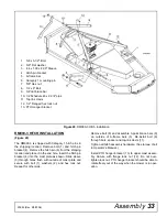
Page 33: ...ve bolt 8 and assemble 3 point brace bars 9 on outside of A frame bars 5 Re install bolt 8 through bars spacer and top link clevis 11 Tighten all hitch assembly hardware See torque chart in Operator s...

Page 34: ...21 to tongue 1 as shown Install ratchet adjustment link 7 between the tongue and height adjustment post on wheel yoke using pins provided with adjustment link The optional hydraulic cylinder may be in...

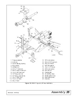
Page 35: ...8 x 5 21 32 Clevis pin 8 1 2 x 5 3 4 Clevis pin 9 1 2 Heavy hex nut 10 1 2 Heavy lock washer 11 1 2 x 3 9 16 Pipe 12 1 2 x 5 1 2 Bolt 13 3 8 x 1 Bolt 14 3 8 Lock washer 15 5 8 x 2 1 4 Clevis pin 16 5...

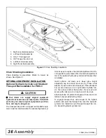
Page 36: ...ment link or the optional hydraulic cylinder and transport bar is installed Install cylinder rod clevis over wheel yoke height adjustment lug and insert clevis pin 3 Place a flat washer 5 over each en...

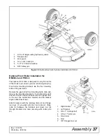
Page 37: ...mine right and left Position these brackets with the highest hole to the rear the middle hole forward and the bracket angle outward as shown Attach brackets with the carriage bolts 3 and flange lock n...

Page 38: ...out the drive on front of deck NOTICE Failure to follow instructions may result in damage Install sleeve 3 on mounting pins and retain with Klik pin Front Caster Wheel Installation for RM990 3 Remove...

Page 39: ...r opposite rear caster wheel Figure 35 RM990 3 Rear Caster Wheel Installation Initial Filling of Gearbox NOTICE Gearbox was not filled with oil at the factory It must be serviced before operating Fail...

Page 40: ...manual safety rules explain their meanings and emphasize the increased safety hazards that exist when safety rules are not followed ___Show customer how to make sure driveline is prop erly installed a...

Page 41: ...Serial Numbers 577001 thru 725410 page 59 Rear 1 2 drive assembly With Tri Lobe Shaft for Serial Numbers 577001 thru 725410 page 59 With Square Shaft for Serial Numbers 577000 and Below page 60 Quick...

Page 42: ...42 Parts 20944 Rev 8 4 2009 RM990 3 P990 3 MAIN FRAME ASSEMBLY COMMON PARTS 63 31 CD3955E...

Page 43: ...5 2 626 ID x 1 85 OD Ball bearing 30 51849 1 Counter cone shield RM990 only 31 24549 3 5 16 SQ x 1 3 4 Key 33 1266 3 16 x 1 1 2 Cotter pin 34 839 3 8 NC x 1 Cap screw GR5 S N 788882 and prior or 34 30...

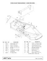
Page 44: ...t link 25 x 1 50 x 45 56 6 64814 1 1 2 Schedule 40 x 2 3 4 pipe 7 1 Universal drive 8 36998 1 PTO hanger bracket 30 3379 1 2 NC x 1 1 2 Cap screw GR5 32 29561 1 2 NC x 4 3 4 Cap screw GR5 33 11900 1 2...

Page 45: ...R5 29 404 1 2 x 5 3 4 Clevis pin HT 30 855 1 2 Extra heavy lock washer REF PART QTY DESCRIPTION 31 1093 1 2 NC Heavy hex nut 32 765 1 2 NC Hex lock nut S N 788882 and prior 33 7035 1 2 Schedule 40 x 3...

Page 46: ...washer 10 1686 4 3 8 NC x 3 4 Cap screw GR5 11 10362 1 1 Sq head vented pipe plug used prior to S N 2000 12 20675 1 Gearbox cover 10GA 6 1 x 6 9 13 20673 1 Gearbox flange mount housing 14 20682 1 1 6...

Page 47: ...includes items 6 7 3 20192 1 Yoke shaft 14N x 15 50 4 154 1 Universal joint repair kit L14R 5 20193 1 Shear yoke 2000 series S N 788882 and prior 5 148 1 Quick disconnect yoke 1 3 8 after S N 788882 6...

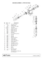
Page 48: ...10 20897 1 Internal retainer ring 81 mm 11 2 Cotter pin 12 57466 2 Snap ring 13 57467 1 Snap ring 14 57373 1 Spacer 35 3 x 48 x 2 5 15 57328 2 Gearbox shim kit 16 57469 1 Castle nut M24 x 1 5 17 20892...

Page 49: ...1 37 ID x 2 83 OD Ball bearing 9 2985 1 4 28 Threaded 905 grease fitting 10 20197 1 1 3 16 Tube drive 14N 18 94 long 11 20196 1 Tubular shield with bearing chain 15 25 long 12 15999 1 Shield bearing...

Page 50: ...4 1 Yoke 1 3 8 6 SP complete with lock collar after S N 788882 12 40766 2 Bearing ring Package of 2 13 40777 2 Anti rotation chain 14 40778 2 Screw Package of 10 17 40779 1 Grease zerk 18 40767 1 Guar...

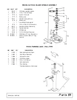
Page 51: ...1 1 3 4 x 2 3 8 x 13 GA Flat washer 9 24521 1 Spindle shaft and crossbar asy 10 24527 2 Spindle blade lock 11 3967 2 QD Blade pin 12 13288 2 1 2 NC x 3 4 Nylok Cap screw 13 24590KT 1 CCW Blade 13 long...

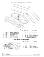
Page 52: ...x 34 75 5 19566 1 Right rear rubber shield plate 6 19567 1 Left rear rubber shield plate 7 19568 2 Rubber belt 3 75 x 48 50 8 19569 2 Link 19 x 1 25 x 48 25 9 6697 54 3 8 NC x 1 Carriage bolt GR5 10 1...

Page 53: ...shield plate 3 20792 1 Right rear chain shield plate 4 20793 1 Left rear chain shield plate 5 4763 60 3 Link chain 1 4 proof 6 4765 96 4 Link chain 1 4 proof 7 1256 8 3 16 x 1 Cotter pin 8 18150 2 3...

Page 54: ...ub with cups 10 1257 1 3 4 Standard flat washer 11 5849 1 3 4 NF Slotted hex nut 12 14133 1 Hub cap with grease fitting 13 6270 1 Straight 1 4 tapered thread grease fitting for hub cap Standard hardwa...

Page 55: ...Bearing cone 7 5624 4 Seal for 1 1 8 shaft 8 52743 2 Caster yoke 9 52741 2 Axle 10 52744 4 752 x 1 125 x 625 HT Bushing 14 21022 1 4 x 2 Spirol pin 15 1972 1 4 28 Tapered thread grease fitting 16 1202...

Page 56: ...earing cup 12 20718 2 13 x 5 x 10 Solid tire includes item 11 or 12 19744 2 13 x 5 x 6 Pneumatic tire includes item 11 13 52743 2 Caster yoke 14 52744 4 752 x 1 125 x 625 HT Bushing 15 52741 2 Axle 30...

Page 57: ...ic hose kit fittings 2 17628 1 1 4 NPT x 108 High pressure hose assembly 3 10290 1 1 4 x 1 4 x 90 Elbow with 1 16 restrictor 4 11893 1 1 2 x 1 4 Pipe reducer bushing Standard hardware obtain locally R...

Page 58: ...4 Tie rod 7 11893 1 1 2 x 1 4 Pipe reducer bushing 8 25494 1 Cylinder butt end 9 923 4 1 4 x 1 3 4 Cotter pin 10 1631 2 1 x 3 5 8 Clevis pin 11 11975 1 1 2 NPT Vent plug 12 26342 1 Cylinder barrel 13...

Page 59: ...N S 1 Shield tube 8 30922 3 Retainer shield 9 30917 1 Chain shield tether 10 30913 1 1 3 8 Push pin set 11 53457 1 Outer shield assembly complete includes items 5 through 9 N S Not serviceable REF PAR...

Page 60: ...e female telescoping 1800 18 38 5 19992 1 Shield Non rotating 2 75 x 19 5 6 15738 1 Shield bearing 7 117 1 Lock pin spring 8 15739 1 Shield tether chain 27 1 2 9 6128 1 1 4 NC Hex lock nut 10 19898 1...

Page 61: ...lf shielded 1800 20 44 1 38 2 19996 1 Shield non rotating 2 50 x 2 50 x 19 9 3 19995 1 Yoke shaft male telescoping 1800 x 20 44 4 15511 1 Universal joint repair kit 1800 5 19745 1 Shear yoke 1800 6 15...

Page 62: ...coil 38 link 3 38214 2 Sleeve 91 x 1 44 x 1 25 4 13563 1 Cap screw 1 2 NC x 6 GR5 5 854 6 Washer flat 1 2 ZP 6 29368 1 Sleeve 50 x 75 x 3 38 7 11900 1 Nut flange lock 1 2 NC 8 29281 2 Sleeve 7 8 x 1...

Page 63: ...1 2 467 634 722 979 1020 1383 Diameter Thread Pitch Millimeters Wrench Size Coarse Thread Fine Thread Diameter Thread Pitch Millimeters Marking on Head Marking on Head Metric 8 8 Metric 10 9 Metric 8...

Page 64: ...HHCS Hex Head Cap Screw HT Heat Treated JIC Joint Industry Council 37 Degree Flare LH Left Hand LT Left m Meter mm Millimeter M Male MPa Mega Pascal N Newton NC National Coarse NF National Fine NPSM...

Page 65: ...Specifications 4 Warranty Product 88 Replacement Parts 1 O OPERATION 10 Attaching Mower to Tractor 10 P990 3 12 Drawbar to Hitch Point Distance 12 RM990 3 Cutting Height Adjustment 11 Tractor Stabili...

Page 66: ...t or noncompliance is discovered or should have been discovered routed through the dealer and distributor from whom the purchase was made transportation charges prepaid WOODS shall complete such repai...

Page 67: ...be returned to WOODS with proof of purchase within thirty 30 days after such defect or noncompliance is discovered or should have been discovered routed through the dealer and distributor from whom th...

Page 68: ...Equipment Company 2606 South Illinois Route 2 Post Office Box 1000 Oregon Illinois 61061 815 732 2141 tel 815 732 7580 fax www woodsonline com 1995 Woods Equipment Company All rights reserved PART NO...

Reviews: