background image

Dealer Service 23

MAN0475 (9/21/2005)

Spindle Assembly 

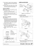
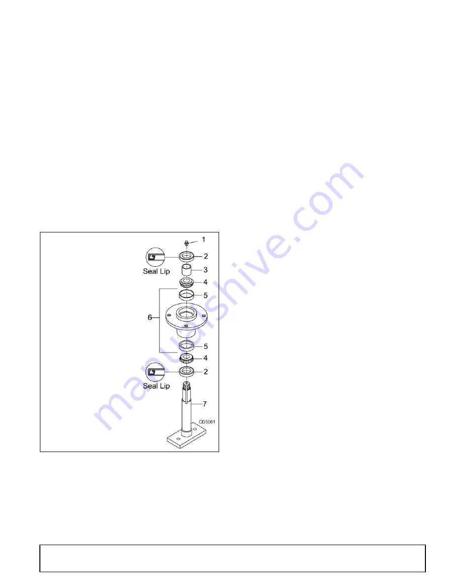
Refer to Figure 17.

Bearing cones and cups are designed to work together.
It is important to position them so bearing cone taper
mates with cup taper.

1. Lubricate new cups with a light oil. Place them in

spindle housing so they will mate with bearing
cones. Cups and cones are a press fit to minimize
wear.

Seat cups securely with a press or place a large
drift in the flat lip and drive them into housing until
cup seats against machined shoulder of housing.

Remove bearing cups from housing by placing a
punch in the slots provided and driving them out.
Alternate punch positions from side to side. Take
care to prevent housing damage.

2. Place bottom bearing cone into spindle with taper

positioned to mate with cup. 

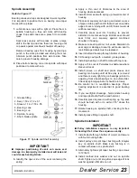
 Figure 17. Spindle and Shaft Assembly

IMPORTANT

■  

Improper positioning of seals can cause seal

damage. An improperly installed seal will leak and
could cause bearing failure.

3. Identify the open side of the seal containing the

spring.

4. Apply a thin coat of Permatex to the area of

housing where seals seat.

5. Install bottom seal with spring up toward center of

housing.

6. Place seal squarely on housing and select a piece

of pipe or tubing with an OD that will set on outside
edge of seal. A tubing with an OD that is too small
will bow seal cage.

7. Carefully press seal into housing, to prevent

distortion to metal seal cage. Bottom seal should
seat firmly and squarely against machined
shoulder in housing.

8. Make sure seal lip did not roll under. Distortion to

seal cage or damage to seal lip will cause seal to
leak. Damaged seals must be replaced.

9. Insert shaft and bearing through bottom of housing.

10. Fill housing cavity with a medium grade grease.

11. Install top bearing on shaft to mate with top cone.

12. Apply a thin coat of Permatex to shaft area where

sleeve will seat.

13. Install sleeve on shaft and press sleeve and

bearing into housing until all free play is removed
and there is a very light drag on bearings (similar to
adjusting front wheel bearings on an automobile).
Check by spinning spindle. It should turn freely.

14. Be careful not to overtighten bearings. Proper

bearing adjustment is essential to good bearing
life.

15. If you overtighten bearings, hold spindle housing

and rap spindle shaft with a lead hammer.

16. Carefully press top seal in with spring up. Top seal

should be flush with or to within 1/16" above the
housing.

17. Rotate housing on spindle shaft, checking for free

movement.

18. Install grease fitting in spindle shaft.

Spindle Installation

IMPORTANT

■  

Pulley installation sequence is very important

for bearing life. Follow the sequence exactly.

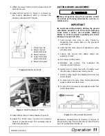
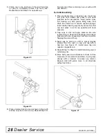
1. Install spindle through bottom of mower and secure

with four mounting bolts.

2. Install pulley and split taper bushing with integral

key on spindle shaft. Make sure bushing is in
contact with sleeve on spindle shaft. 

3. Alternately tighten split taper bushing cap screws

to 12 lbs-ft.

4. Install toothed lock washer and nut on spindle

shaft. Tighten nut until snug. Bend up edge of lock
washer against a flat side on nut.

1. Grease fitting

2. Seal, 1.50 x 2.12 x .31

3. Sleeve, 1.14 x 1.50 x .55

4. Bearing, cone

5. Bearing, cup

6. Spindle, housing 

7. Shaft, blade spindle

Summary of Contents for PRD6000, PRD7200, PRD8400

Page 1: ...OPERATOR S MANUAL 2 FRONT PREMIER REAR DISCHARGE MOWERS MAN0475 Rev 6 22 2007 Tested Proven Unbeatable PRD6000 PRD7200 PRD8400...

Page 2: ...er check the Dealer Locator at www WoodsEquipment com or in the United States and Canada call 1 800 319 6637 The equipment you have purchased has been carefully engineered and manufactured to provide...

Page 3: ...RVICE 16 TROUBLE SHOOTING 20 DEALER SERVICE 22 ASSEMBLY 29 DEALER CHECK LIST 33 PARTS LISTS 35 BOLT TORQUE CHART 46 BOLT SIZE CHART ABBREVIATIONS 47 INDEX 48 PRODUCT WARRANTY INSIDE BACK COVER REPLACE...

Page 4: ...ding removed The purpose of this manual is to assist you in operating and maintaining your mower Read it carefully It fur nishes information and instructions that will help you achieve years of depend...

Page 5: ...nes If guards do not rotate freely on drive lines repair and replace bearings before putting equipment into service Power unit must be equipped with ROPS or ROPS cab and seat belt Keep seat belt secur...

Page 6: ...ays comply with all state and local lighting and marking requirements Never allow riders on power unit or attachment MAINTENANCE Before working underneath carefully read Oper ator s Manual instruction...

Page 7: ...ion Make sure shields and guards are properly installed and in good condition Replace if damaged Wear gloves when installing belt Be careful to prevent fingers from being caught between belt and pulle...

Page 8: ...decals can be ordered free from your Woods dealer To locate your nearest dealer check the Dealer Locator at www woodsonline com or in the United States and Canada call 1 800 319 6637 11 57123 9 Red Re...

Page 9: ...and hands fingers feet and other body parts could be crushed or pinched between tractor and implement Operate tractor controls from tractor seat only Do not stand between tractor and implement when t...

Page 10: ...ns disconnect driveline raise mower securely block up all corners with jackstands and check stability Secure blocking prevents equipment from dropping due to hydrau lic leak down hydraulic system fail...

Page 11: ...damage to mower and drive 1 Level mower from side to side Check by measuring from mower frame to the ground at each deck rail 2 Verify that the same amount of spacers are under all caster arms 3 Loos...

Page 12: ...in two positions Figure 8 shows the two possible configurations for the PRD6000 and PRD7200 front caster arms The inner position allows the outside edge of the mower to be used for trimming under shru...

Page 13: ...is interference on models PRD6000 and PRD7200 mount front casters in the outer position If interference continues adjust mower hitch plate E as shown in Figure 6 NOTE On model PRD8400 caster wheel wid...

Page 14: ...ct and clear area of stones branches or other hard objects that might be thrown causing injury or damage Extremely tall material should be cut twice Set mower at a higher cutting height for the first...

Page 15: ...g activated locking pin or collar slides freely and is seated firmly in trac tor PTO spline groove ___ Make sure the driveline guards and tether chains are in good condition Guards must rotate freely...

Page 16: ...he mower four total must be installed before working underneath When blocking you must consider overall stability of the unit Just blocking under the unit will not ensure your safety The working surfa...

Page 17: ...r wheels 8 Hours 3 Caster Pivot Four wheels 8 Hours 4 Left Spindle Access through hole 24 Hours 5 Shield Bearings 8 Hours 6 Rear U Joint 8 Hours 7 Gearbox Fill to center of horizontal shaft with SAE 9...

Page 18: ...lt around pulley B idler C and pulley D as shown 4 Make sure belt is on drive pulley A route around idler F and connect idler spring to lug I on deck 5 Grasp belt between spindle pulley E spring loade...

Page 19: ...If this machine is not equipped with full chain shielding operation must be stopped when anyone comes within several hundred feet Check that chain shielding is in good condition and replace any damage...

Page 20: ...wet for mowing Allow grass to dry before mowing Blades unable to cut that part of grass pressed down by path of tractor tires Slow ground speed of tractor but keep engine running at full PTO rpm Cutt...

Page 21: ...s Check belt for free travel in pulleys Check under mower and around blade spindle shaft for wire rags or other foreign material Clean all material from under mower Frayed edges on belt cover Belt mis...

Page 22: ...pindle repair requires special skills and tools If your shop is not properly equipped or your mechanics are not trained in this type of repair you may be time and money ahead to use a new spindle asse...

Page 23: ...id not roll under Distortion to seal cage or damage to seal lip will cause seal to leak Damaged seals must be replaced 9 Insert shaft and bearing through bottom of housing 10 Fill housing cavity with...

Page 24: ...Gasket or equivalent Leakage can occur at the vertical or horizontal gaskets and shaft seals Leakage at the horizontal gasket or seal can be repaired without removing the gearbox from the cutter Seal...

Page 25: ...using through this opening 3 If the leak occurred at either end of horizontal shaft remove oil cap 20 and or oil seal 19 Replace with new one see Seal Replacement page 24 Horizontal seal should be pre...

Page 26: ...d 2 Wash housing and all components thoroughly Select a clean area for gearbox assembly Replace all seals bearings and gaskets All parts must be clean and lightly oiled before reassembling 3 Insert ou...

Page 27: ...the top of the mower deck to the center line of the drive pulley must be 2 7 16 1 32 This is a critical dimension and must be carefully adjusted for proper belt life Add or subtract shim washers unde...

Page 28: ...areful not to disturb needle bearings Insert another bearing cup directly across from first cup and press in as far as possible with hand pressure 2 Trap cups in vise and apply pressure Be sure journa...

Page 29: ...own hydraulic system failures or mechanical component failures Always wear relatively tight and belted clothing to avoid getting caught in moving parts Wear sturdy rough soled work shoes and protectiv...

Page 30: ...rm posi tions 4 Attach front caster arm in desired position and tighten snug against deck bracket Torque Caster Arm Hardware 1 Lift mower off shipping pallet and set on a hard level surface This allow...

Page 31: ...plate 14 Bolt carriage 3 8 NC x 1 15 Nut flanged lock 3 8 NC Figure 33 Chain Shield Installed 1 Install chain shielding plate 3 to rear mower frame as shown 2 Secure with carriage bolts 14 and flange...

Page 32: ...sing cap screw 4 two flat washers 5 and nut 7 Attach opposite ends of chains 2 to rear mower frame as shown Cut chains to length see chart above Vary length slightly as desired Twist chain to make fin...

Page 33: ...resent Operator s Manual and request that customer and all operators read it before oper ating equipment Point out the manual safety rules explain their meanings and emphasize the increased safety haz...

Page 34: ...34 Notes MAN0475 9 21 2005 NOTES...

Page 35: ...EMBLY 38 DRIVESHAFT ASSEMBLY WALTERSCHEID TWO LOBE 39 DRIVESHAFT ASSEMBLY COMER PROFILE BLADE SPINDLE ASSEMBLY 41 REAR CHAIN SHIELDING ASSEMBLY 42 FRONT ROLLER ASSEMBLY OPTIONAL 42 QUICK HITCH KIT OPT...

Page 36: ...36 Parts MAN0475 9 21 2005 PRD6000 PRD7200 PRD8400 MAIN FRAME ASSEMBLY Rev 12 23 2005...

Page 37: ...t Shield Right PRD6000 or 25 1014418 1 Belt Shield Right PRD7200 or 25 52874 1 Belt Shield Right PRD8400 26 1014417 1 Belt Shield Left PRD6000 or 26 1014418 1 Belt Shield Left PRD7200 or 26 52875 1 Be...

Page 38: ...Cotter B4 x 50 10 57466 2 Snap Ring 11 20895 1 Snap Ring 45 mm 12 57373 1 Spacer 35 3 x 48 x 2 5 13 57328 2 Kit Shim 60 3 x 71 6 14 57468 1 Nut Castle 15 51946 1 Nut Castle M24 x 2 16 57328 1 Kit Shim...

Page 39: ...er Profile 7 40573 1 Yoke Outer Profile 12 40776 1 Bearing Ring Kit set of 2 13 40777 2 Chain Guard Anti Rotation REF PART QTY DESCRIPTION 14 40778 1 Screw Guard Retainer Pkg of 10 17 40779 1 Grease Z...

Page 40: ...2 38478 2 Cross and bearing kit 3 1019442 1 Outer cone fix ring 4 30922 6 Protection fixing screw 5 1019444 1 Inner cone fix ring 6 30917 2 Chain shield tether 9 1001340 1 Lock collar repair kit 10 10...

Page 41: ...9899 Bearing Cone 11 52882 Blade Spindle Housing with Cups 12 29898 Bearing Cup 14 52852 Shaft Blade Spindle 16 1001513KT Blade Kit High Suction 21 In set of 3 PRD6000 16 1008199KT Blade Kit High Suct...

Page 42: ...for PRD8400 REF PART QTY DESCRIPTION 3 55345 1 Shield Chain Plate for PRD6000 only or 3 53554 1 Shield Chain Plate for PRD7200 only or 3 52885 2 Shield Chain Plate for PRD8400 only 14 Bolt Carriage 3...

Page 43: ...glasses or goggles to prevent eye injury while drilling holes 4 Clamp mulching kit in place Make sure baffles are completely closed off by the kit 5 Inspect fit up to confirm that there will be no co...

Page 44: ...692 2 Link Offset 38 x 2 0 x 15 2 1005401 2 Chain 3 8 Proof Coil 38 Link 3 1016517 2 Sleeve 94 x 1 44 x 1 94 4 13563 1 Screw 1 2 NC x 6 HHCS GR5 5 854 6 Washer 1 2 Flat 6 29368 1 Sleeve 50 x 75 x 3 38...

Page 45: ...GR5 4 11900 Nut 1 2 NC Flange Lock Obtain Locally INSTALLATION INSTRUCTIONS 1 Locate and drill three 17 32 holes using the dimensions from the drawing and table above 2 Secure skid shoe with three ca...

Page 46: ...1 2 467 634 722 979 1020 1383 A SAE SERIES TORQUE CHART SAE Bolt Head Identification SAE Grade 2 No Dashes SAE Grade 5 3 Radial Dashes SAE Grade 8 6 Radial Dashes A METRIC SERIES TORQUE CHART Metric...

Page 47: ...37 Degree Flare LH Left Hand LT Left m Meter mm Millimeter M Male MPa Mega Pascal N Newton NC National Coarse NF National Fine NPSM National Pipe Straight Mechanical NPT National Pipe Tapered NPT SWF...

Page 48: ...OPERATION Adjustment Cutting Height 11 Cutting Height Chart 12 Tractor Top Link 12 Attaching Mower to Tractor 10 Cutting Height Adjustment 11 Cutting Height Chart 12 Front Caster Arm Configuration 12...

Page 49: ...f of purchase within thirty 30 days after such defect or noncompliance is discovered or should have been discovered routed through the dealer and distributor from whom the purchase was made transporta...

Page 50: ...iscovered routed through the dealer and distributor from whom the purchase was made transportation charges prepaid WOODS shall complete such repair or replacement within a reasonable time after WOODS...

Reviews: